PoC: Custom MHS heatsink pcb (for my Obi TPM)
was going to post this in the 'idea thread'.. but figured just make its own thread for it..
another step in my OBI TPM saga.. lol
trying to keep the size as accurate as 'I' can, and still having it be somewhat MHS based at the core...
I was stuck on finding out a way to use the stock switches as real, functioning switches for my hilt.
(Ive always been keen on the all-in-one core ideas... but have the switches on/in the core and some sort of cap/plunger on the outside has always been a PITA for me... here and there a few ideas have came out/been used)
for the OBI.. when everything was done,.. the switch holes would go (more or less) at the same exact level of the MHS heatsink.. so I need to adjust that a bit.. and also find a way to mount some switches in that area..
I had mulled over Madcows switch approach. but just wasnt a good fit..
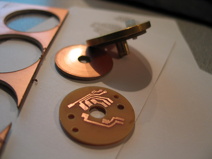
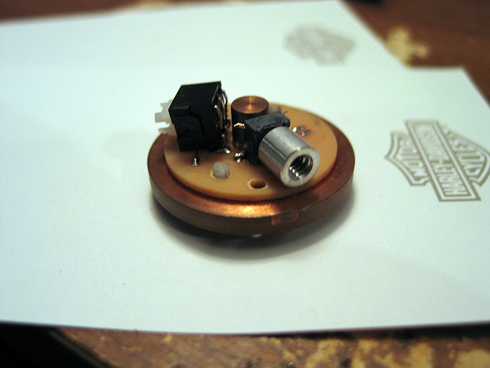
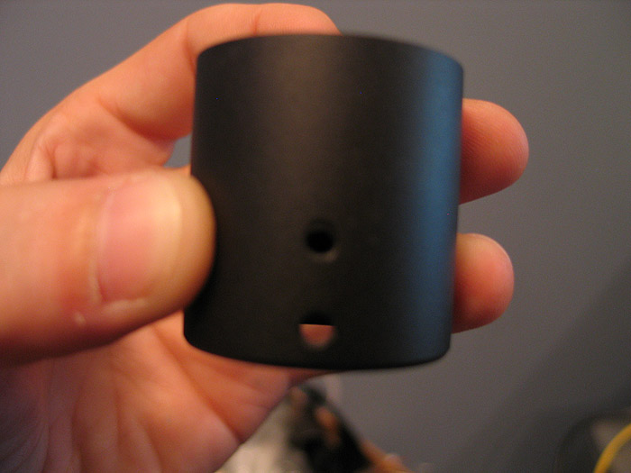
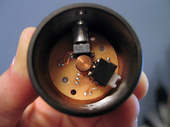
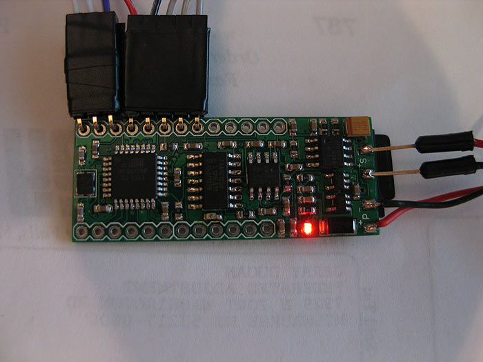
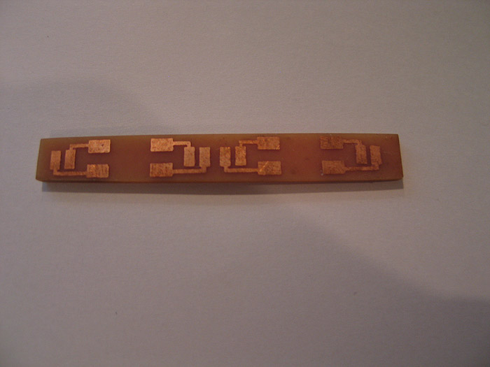
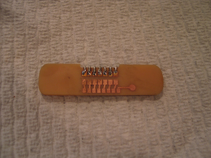
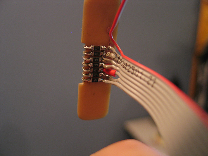
so I came up with a custom, round PCB, that mounts to the underside of the heatsink..and is secured using the same nylon screws that hold our luxeon star pcbs. (MHS hack!)
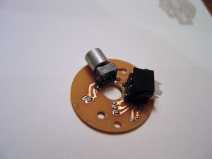
here is my prototype..
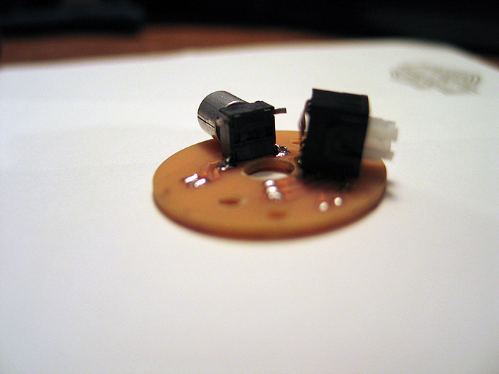
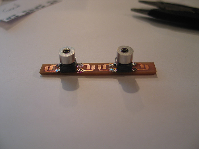
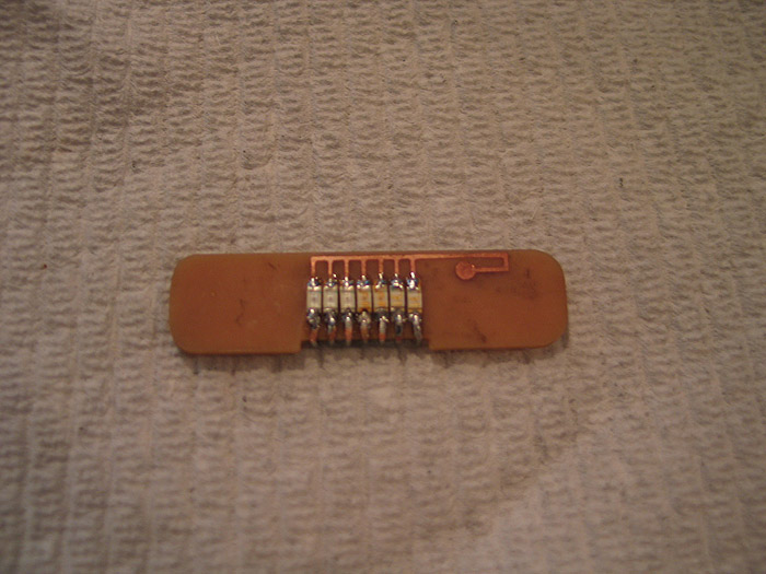
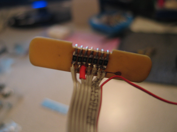
the bike valve switch will have an SMD led in it.. (like they normally do).. to light up the purple gem in the valve end. I just didnt put it back in yet..from doing the momentary mod to the switch (latching by default)
I also didnt clip the extra leads from the switches yet.. but I believe the idea is sound.. and can open up the doors for others to use the same idea/approach.. (nned to mount a unique switch?.. make a pcb for it!)
I posted a tut on how to etch your own pcbs..etc.. using your home laser printer and photopaper..
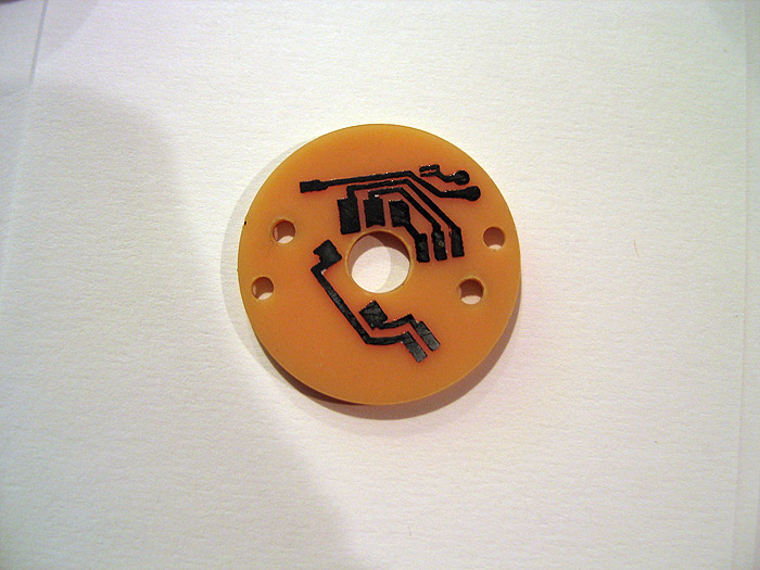
1.) make pcb deisgn in photoshop..
2.) print to photo paper
3.) iron to your copper clad board.
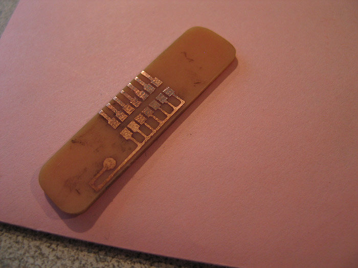
you get this:
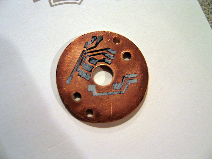
etch and you are left with your laser printer traces (covering the copper underneath)
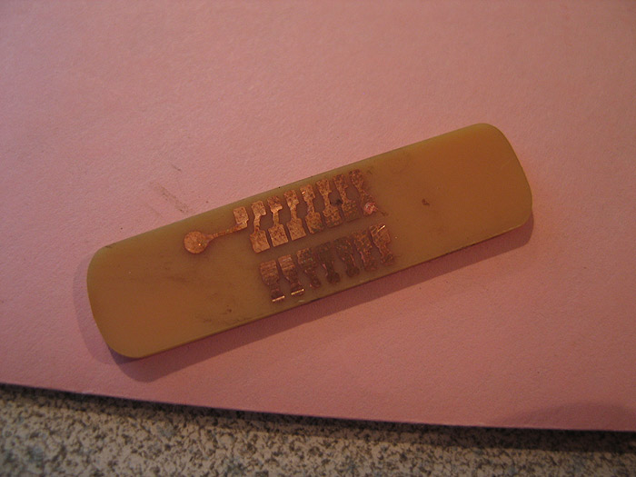
remove toner: (pcb is left)
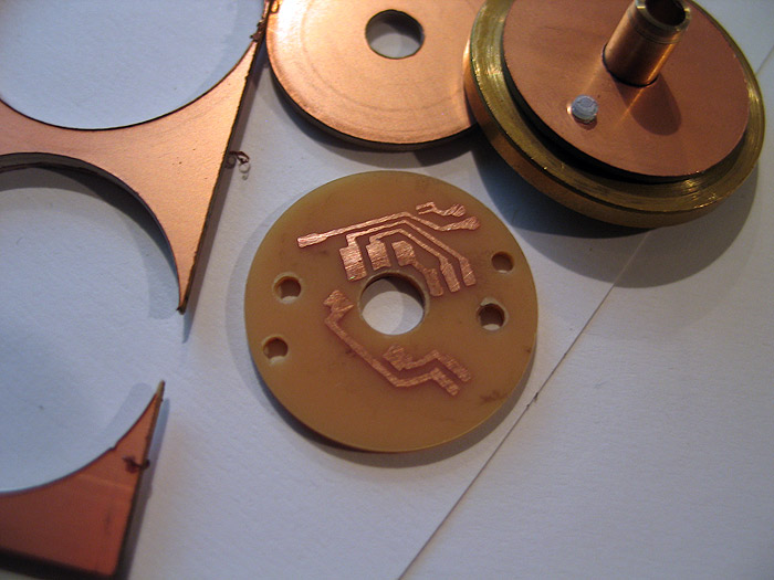
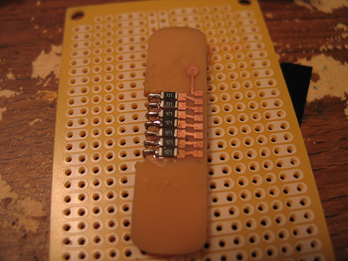
Like Erv taught us.. pre-tin folks!
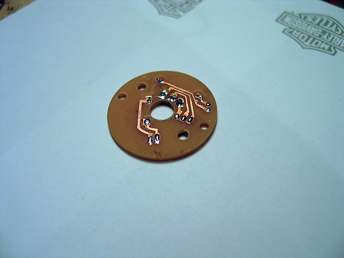
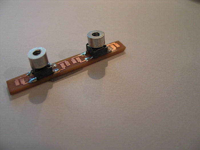
bend my switch leads underneath..and the other row down:
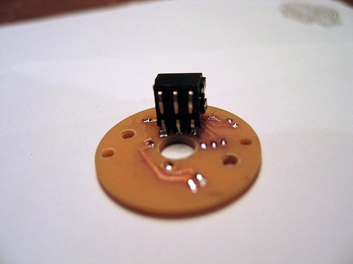
other switch:

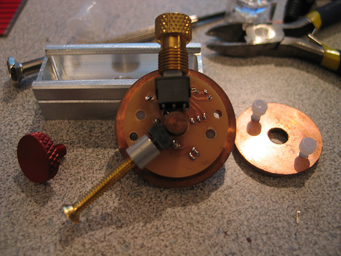
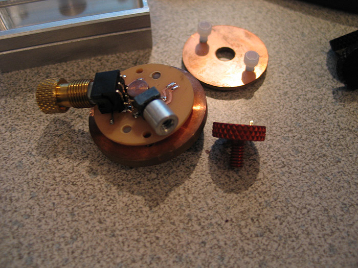
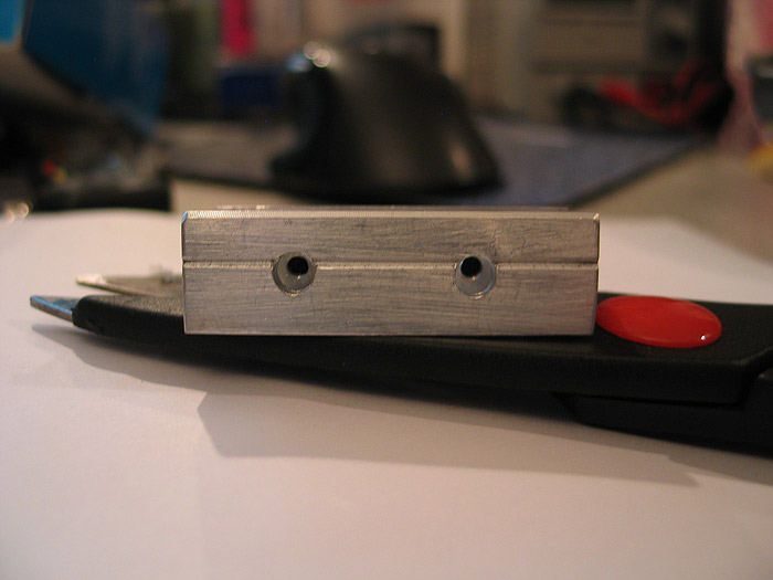
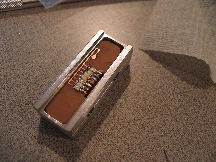
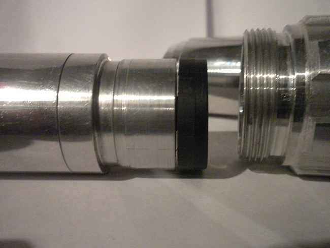
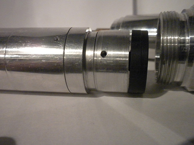
on heatsink:
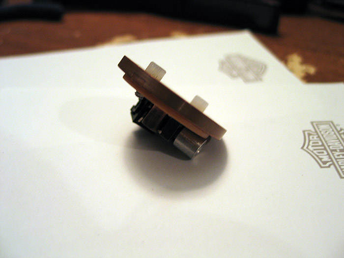
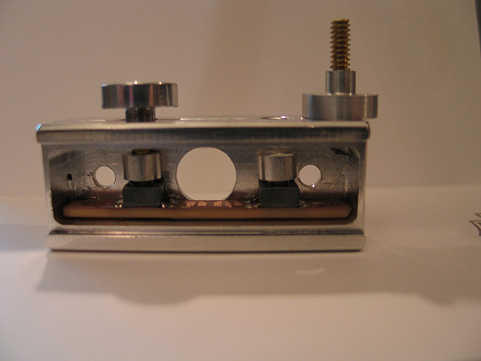
I dont have a red thumbscrew with the correct threads yet.. but you can see it mocked up there.. (screws right in from outside of hilt)
when heatsink is in MHS part.. it lines up with the holes perfectly.. (cant see it so good in pic_ =(
feedback always welcome..
hope this helps others get past road blocks in their projects!
thanks
S.C.A.B development…

Over the 'years'.. (since I was first turned on to the RFX project/platform).. I fell in love with the idea of a generic platform for the user use as they saw fit.
motors, leds, rfid...whatever the project was.. a nice, simple, generic platform for users to 'tweak' and customize seems like a great idea to me.
with RFX basically defunct/dead... I turned toward the Arduino platform. Had a huge following, lots of examples.. and quite easy to get up to speed on basics..etc.. (even without an electronics background)
The problem with the Arduino platform (as is).. is that its purpose (to me) is for developing/prototyping your projects.. but not to be used in the end application.
why? due to size.. and price mainly for me.. (although other Arduino variants can come in smaller sizes.. the price is includes extra development stuff you may not use in your final projects...etc... and not to mention a minimal Arduino circuit can be made for under $7.00 bucks!)
And getting an Arduino to play audio isnt done easily (by default)..
****(although now I just tested a super easy PWM based audio output library.. doesnt use any DAC or AMP.. and the quality is pretty decent for what it is!)
SO I began to teach myself Eagle.. (not easy for me unfortunately..but after some time I got more comfortable with it)..
and laid out some stuff.. and finally felt confident enough to start making my own PCB's and having the shipped to me.. (instead of the old DIY home brew etch approach)
So here I am documenting my process.. (and failures) along the way.. ![]()
a qcuik summary of the things I had to learn.do/involved..
*need to make a the schematic/circuit layout in Eagle
*hope its correct or have others look it over (check against design rules too)
*order the pcb's (sending the exported GERBER files form Eagle to your pcb fab house of choice)
*order a stencil (which is used to layover the pcb and smear solder paste over it to get it applied to the exposed pads through stencil)
*place parts on pcb (tweezers!!!!)
*re-flow pcb in oven
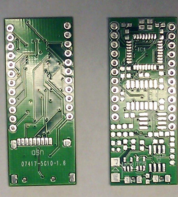
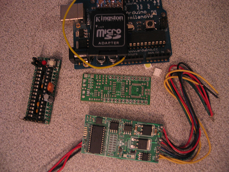
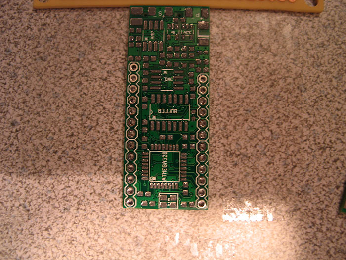
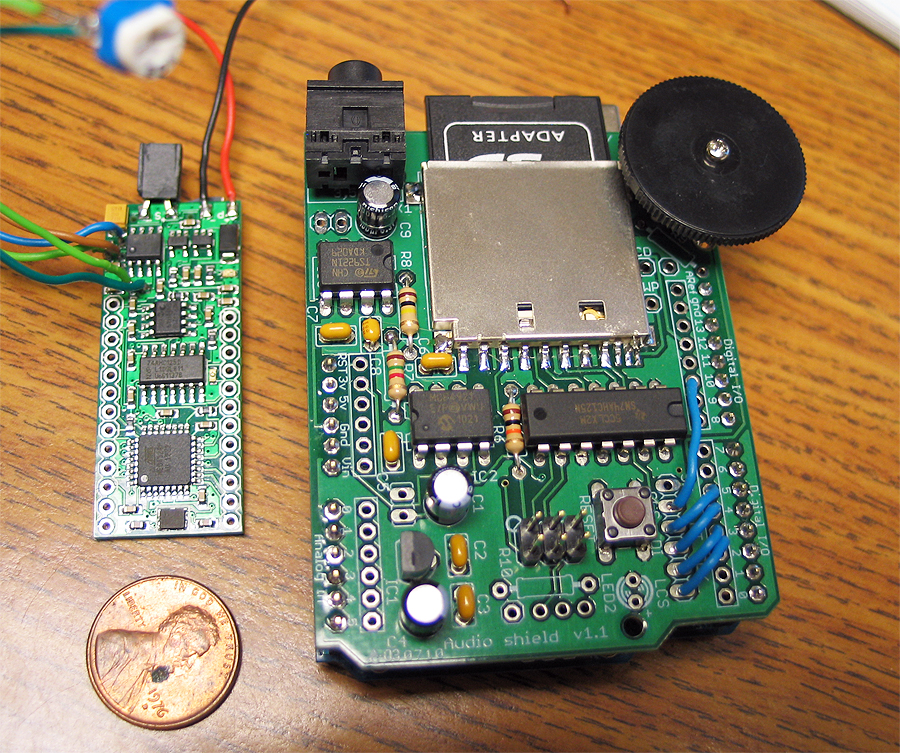
This was my first iteration.. using a different DAC than the schematic I was using as my guide:
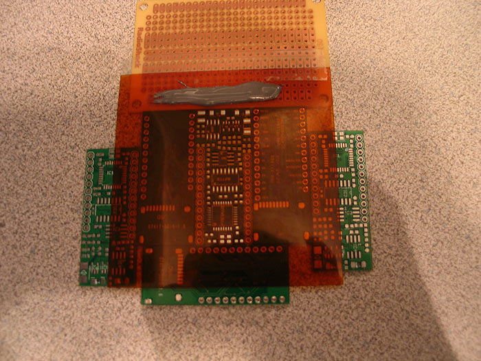
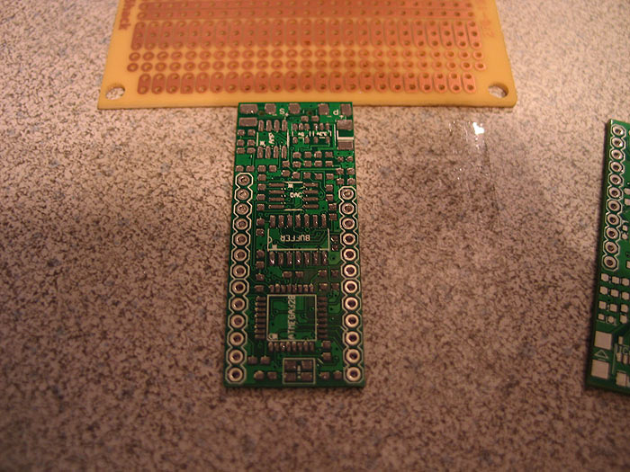
Here was my FIRST generation of pcb's I got made:
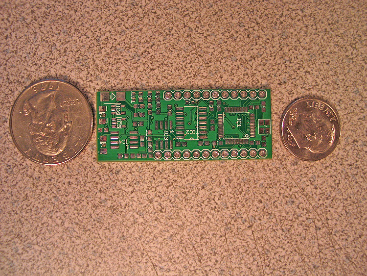
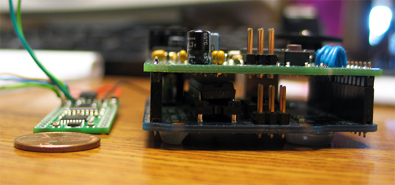
Here is the pcb compared to other stuff.. an Arduino, a smaller minimal Arduino kit..and I think an US 2.5 board:
here I applied my solder paste.. and populated the board with its components..etc. and re-flowed in my wal-mart toaster oven!!
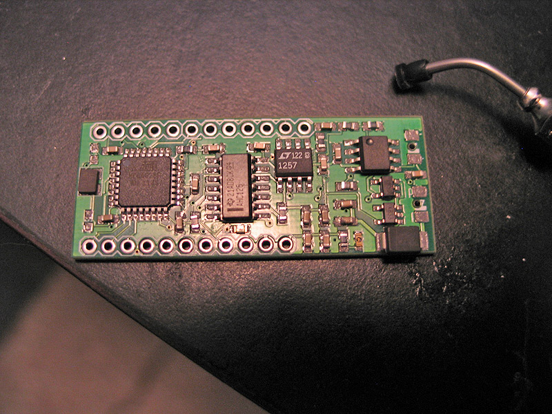
re-flowed:(done)
I had even tried to fix it by testing jumper wires to the default I/O pins..etc.. (no go)..
Well long story short.. after posting and asking....I just couldnt get it working with the DAC I had chosen..maybe someone else could have?? no clue.. (DOH.. should have just followed along..lesson learned)..which I guess is good.. as I had a few other mistakes as well.. =( SO I started over.
In the end, all I had was a tiny Arduino circuit..with on-board uSD socket.. nice.. but no audio output. ![]()
So lets go version 2!!
I got mew pcb's made... got a new stencil made..etc.. and started again.
Here is the process "I" did:
apply the solder paste, using stencil:
remove stencil.. examine paste placement on pads: doesnt need to be PERFECT as the heat from pads will pull solder towards it..etc:
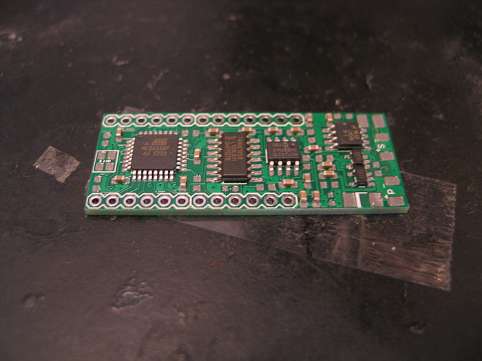
Then populate board: (those TQFP chips are a PITA sometimes!!)
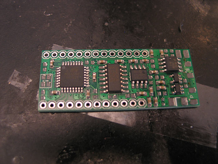
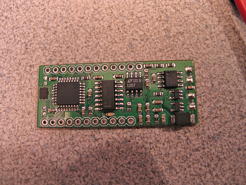
Stick it in the toaster for a bit.. (you can see the solder melt and get shiny)
and when you are done you get a finished board..
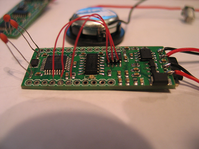
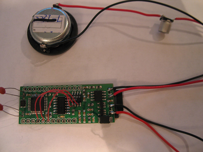
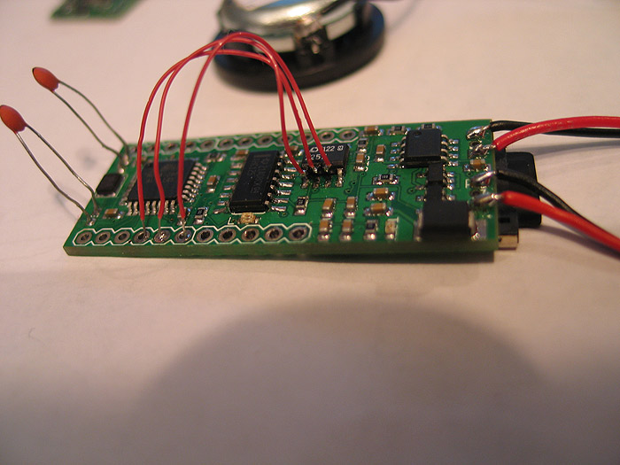
Here are some size shots and comparison shots against a full size Arduino & WaveShield (which is what my custom board is together..those two boards in one)
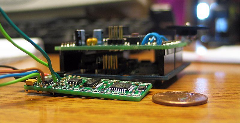
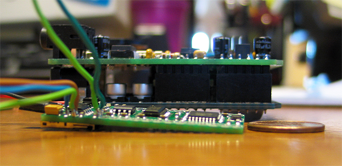
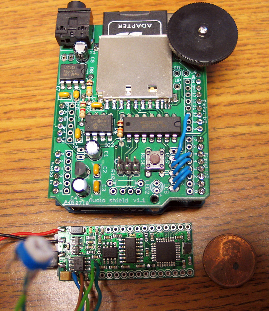
in the last pic you can see some pots wired inplace of some resistors.. I did this so I could dial in not only the volume.. but play with the filter/range, so things didnt sound so muddy/muted..
when done flash the board with whatever code you wrote to control/do whatever it is you need done.
thanks for looking.. was a fun project..
MHS [modified] control box (my entry in cram-fu)
been playing around with a few ideas over the years.. and have worked on a few control box ideas/projects as well...
this one is based off an MHS control box.. with some 'modifications' ![]()
things to note:
*has two switches (main and aux) in it.. (one the 'side' of the box.. with custom switches and switch caps/stems
*custom PCB was created for them to mounted, to and mounted to the inside of the box.
*has a 1.3mm recharge port in it
* has custom smd led bar graph (custom made pcb for this as well)
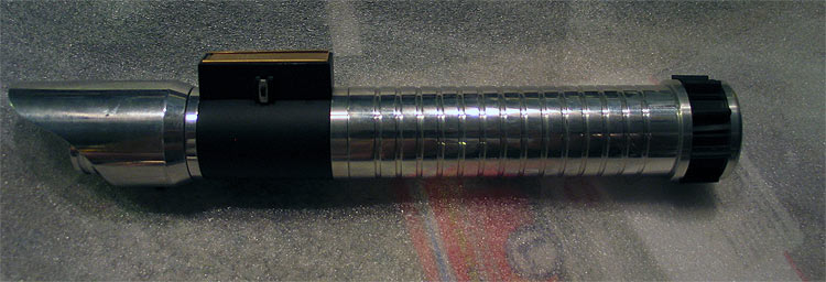
pretty has everything a hilt needs, all located in the......... 'control box' ![]()
posting my mock up pics... if things work out good.. (which it look sot be great even).. I'll break it down again.. re-fine...and buff/polish and powder coat for the finished product.
hopefully this gives some ideas for everyone else... make things work for you!.. make what you need...
lets begin:
1.) take your favorite drawing app and make a PCB design.. no special tools.. draw BLACK lines/traces and pads where you want 'copper' to be..
get your copper clad board/section..
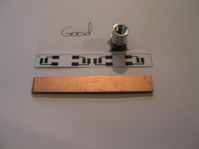
2.) print out image on glossy photo paper.... iron/transfer image/toner to the copper board.. rinse under water to remove paper.. soak in etchant to remove exposed copper:
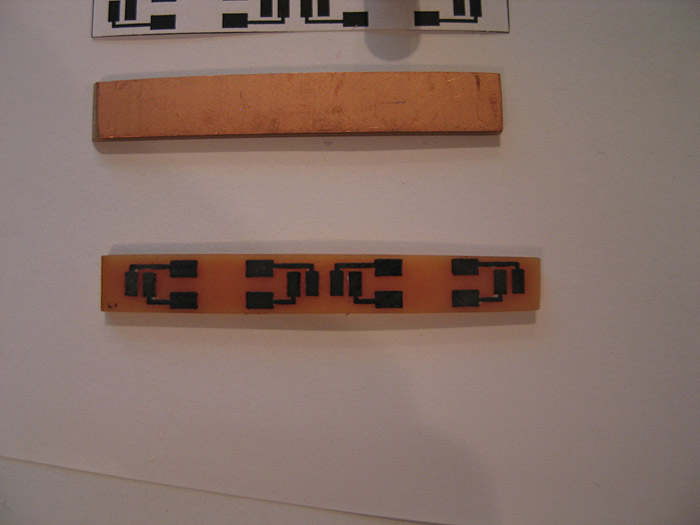
3.) after exposed copper is gone.... use a q-tip and some mail polish remover to remove the toner from the pcb... (revealing the copper/pcb under neath)
***(all this above has been posted many times before.. and shame on you for not trying it!... this could have saved your ass in that 'one' project!) =)
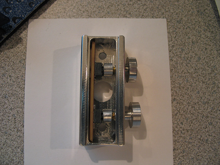
4.) mounted my modified switches to their PCB.. (these have the threaded tops on them for external switch caps to be used form outside the hilt.. keeping the main core/chassis/box internals standalone)
several solder pads depending on the need/space available
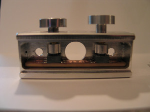
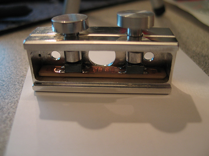
5.) mounted (mocked up) in the control box:
6.) (although it looks 'off' its really just the pic.. things line up great!)
side view of holes and where the switch tops are
7.) top (custom) pcb made..for the led bar graph.. (this posed a problem due to space.. and the fact that I wanted each led to be addressable for either all direct drive..'or' for CF led.txt sequence..etc.. not to mention trying to do double sided board without through hole plating.. (making my own)..
again.. space was concern.. (both sides)
I think an led (possible two) got ruined by heat? or something.. but Im going to replace them real quick. (as they only light up partially)
in the end it will be black box.. aluminum top plate and aluminum switches on the side of the box.
the top 'smd led bra graph' pcb/portion
this is where each resistors goes: (bottom of board)
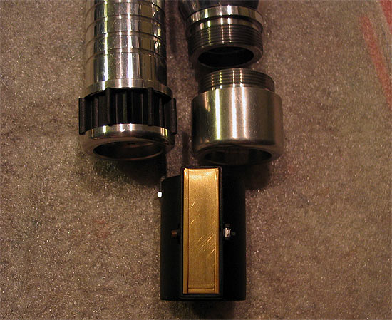
quick mock up:
(again the switch pcb is in place already.. the custom pcb's are almost forming a box to support each other
---------------------------------------------------------------------------------------------------
got a couple hours the other night to finish 95% of it up... (I think 'real' professional PCB's would serve best here)
got the bottom half of the bar graph competed (resistors soldered, wires soldered..etc)
used 1206 resistors.. all I had at the time.. (yesterday my 0603's came.. had I had those in my plannign stage..I think everything might have been topside mounted....oh well v2 I guess..lol..this is my PoC)
still not quite sure how/where to tap the V++ to.. I have a few ideas...not a big deal though any place will work) ![]()
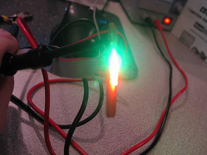
quick test of being lit up.. (had to replace 2 leds as I think they were 'damaged' by initial placement? maybe soldering too hot? different bin? one was of color.. when lit up bright..then gradually died out after a few seconds)..anyways replaced them
2 x green
2 x yellow
3 x red
each resistored, each individually addressable... (so can be direct driven, used with CF, or as PLI) =)
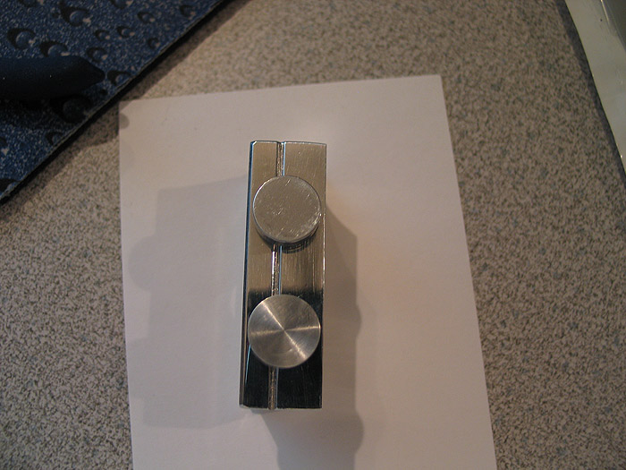
quick mock up of the side/switch PCB inside the box. and the switches/caps/stems I made for them.. (still need to be shortened a bit..but they are close enough to work and show the effect/style)
more pics of the 'switch caps/stems'

the pcb's took about 30 minutes total to make.. (probably another 15 prior on trial and error on printing out paper copies and doing size checks)
now that I feel the idea is 'sound' I'll go back and plan it out a bit better.. (this is supposed to still have recharge port added..but Im not sure after implementing things this far it will make the cut)
time to break it down.. pc the control box BLACK..
buff/polish the 'switches'...
and complete the 'top'.. which is an already sized aluminum strip that sits flush like any normal 'card stock'
there is NOW window cut/milled out of it yet through for the bar graph.. =(
enjoy.
AoF Pommel (mod)

AoF Pommel (mod)
Got some pommels made from Randy a few (years?) back now...
they were oversized (OD).. because most MHS pommels were stock OD..
it is very similar to the Jay-Gon pommel #10 that is in production now..
I like them because:
a.) using a shroud/sleeve/overlay isnt BIGGER than the pommel OD now..
b.) it helps 'lock' in overlays because they cant slip past/over the pommel..
You can see an original one on the right...and the mod'd one on the left.
(some turning down..and trimmed up t-track)
on a hilt/extension section:
Close ups:
R&D: Proof of Concept bearing chassis/core mounts
Being as its winter here..and I doubt I'll get in the garage much, anytime soon..
Wanted to post this idea/concept I had in my head..
while the pics are of a 'core/tube' type chassis this same concept could be used to an open 'sled' type chassis as well.
I talked about this with Fender a bit as well.. although the reverse sound one is not 'pictured'..
I think the idea is sound.. and this is just a roughed out idea..(including the cuts!!) ![]()
Im sure someone can tweak/fine tune.. find a better way. (in theory, a bearing wouldnt even need to be used..but makes it smoother)
Pros:
nice way to secure your core/chassis to your pommel for easy removal
no twisting wire problems
Cons:
mod'ing the speaker holder is PITA.. because the stock speaker OD is big.. I ruined s peaker mounted.. and that one pictured 'was ruined' but salvaged..lmao
in certain pommels, it wont work. (to close to end for insert)
not a lot of resonance
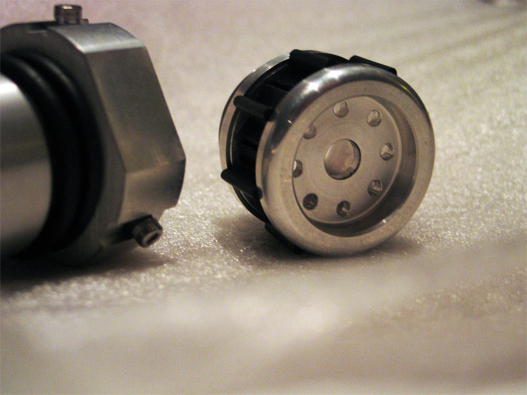
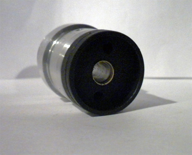
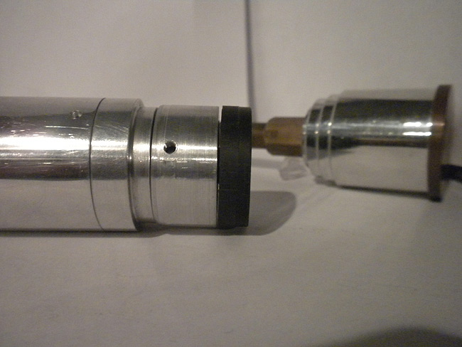
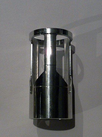
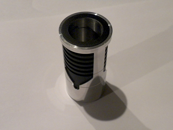
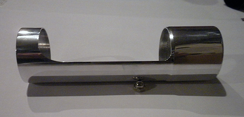
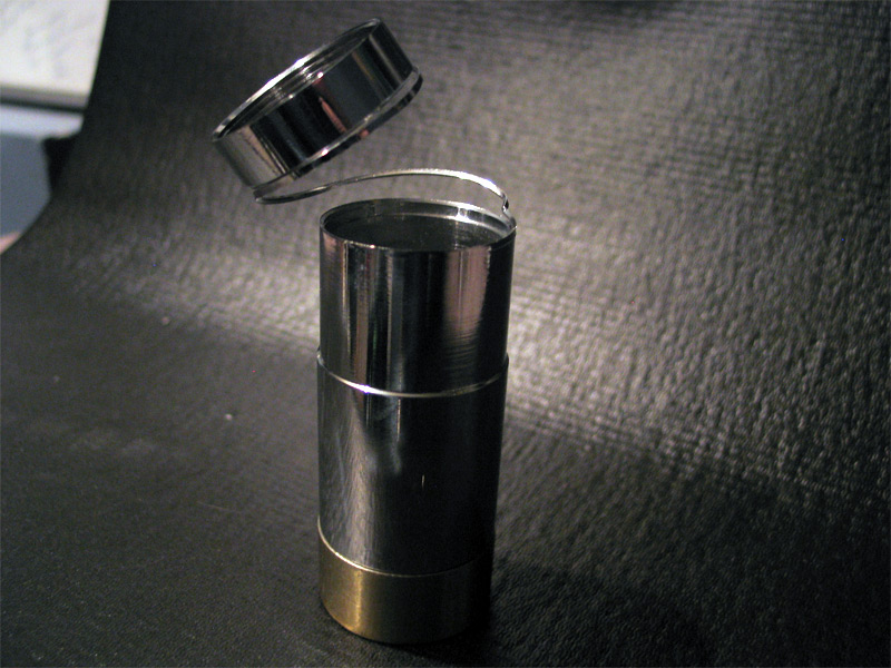
Together view: (not in pommel...but a possible end result could be)
Here is I have my 'core' (main tube) that can hold soundboard & batteries.. the top portion is just added from another past project.. (but is one possibility)..
that top part also have a bearing in it.. and can 'spin'
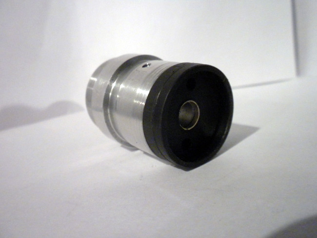
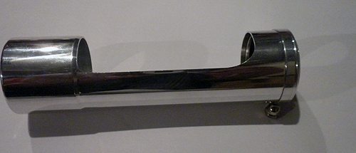
The 'main' part..(together)
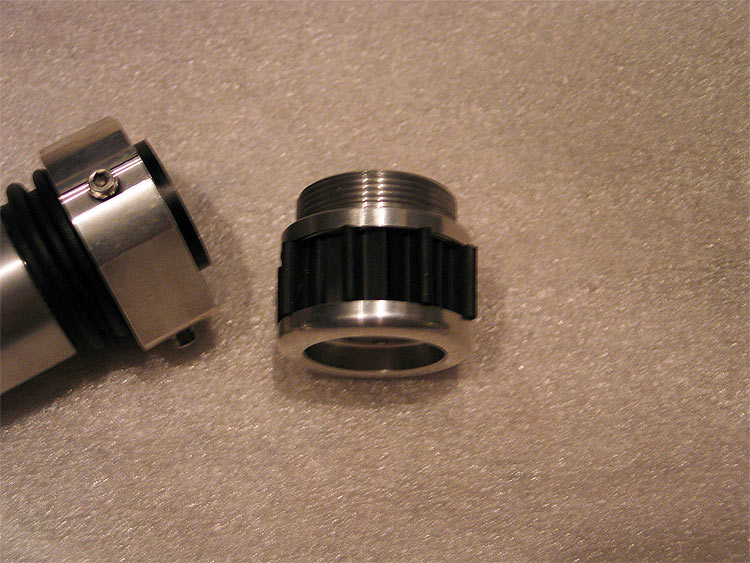
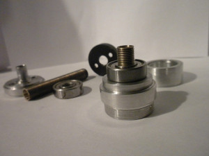
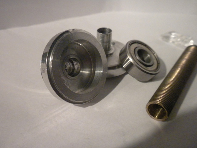
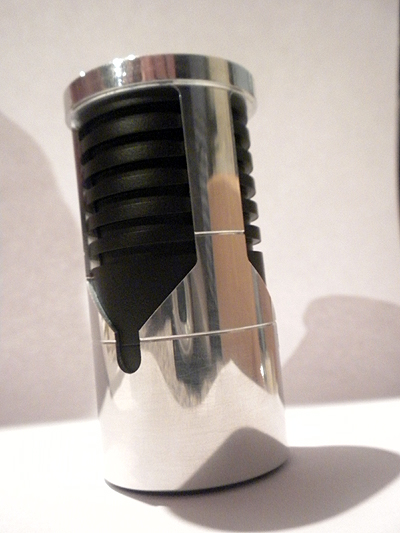
The main part(s) (what is consists of)
turned 'stem' to fit bearing.. (can see similar in background)
Bearing got on stem..
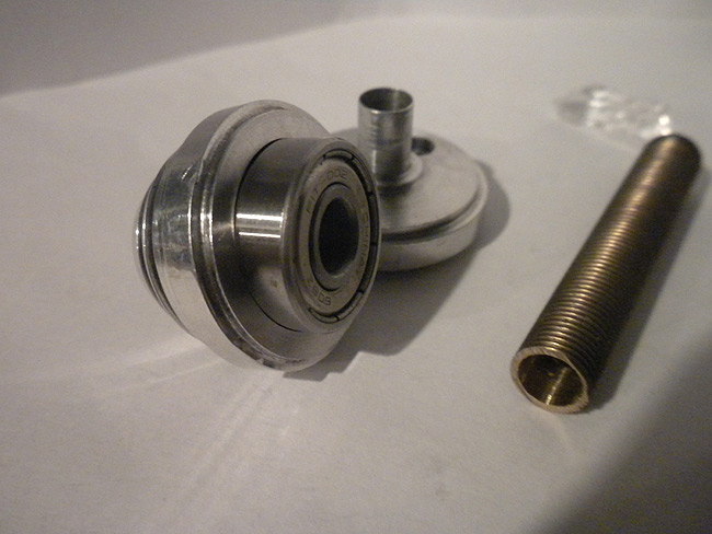
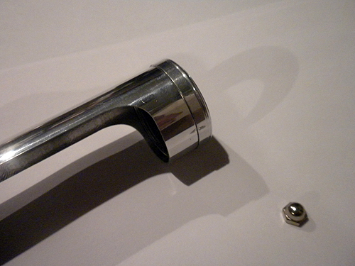
I cut a piece of some external threaded tubing I had NPT 27 tpi I think?.. hollow..
that is actually press fit on there..and is not coming off.. but could be glued just as well little dab only..
it helps keep the bearing in/down... and the threaded part is used to secure the back of the MHS speaker mount.. (NPT 27 tpi tap...I'll have to look up exact size off hand)
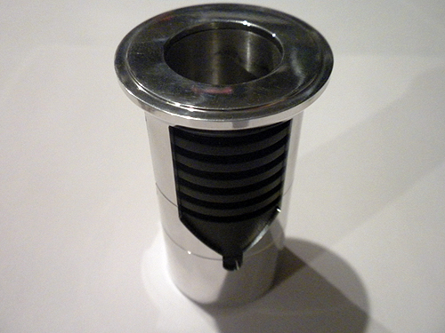
the MHS speaker mount is turned to OD that fits INSIDE the pommel ID...easier to just bore out the pommel a bit though to be honest..save your speaker mounts from being wasted..lol.. hard to leave a 'wall' to snap the speaker into
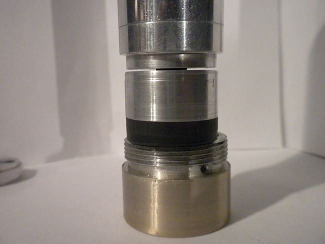
there is a 'ring' with the ID of the bearing OD.. and the OD of a pommel ID
this slides over everything (stem, bearing, NPT secured threaded end)..and has hole tapped so set screw locks ring to bearing..
now you have your free spinning 'ring' that the pommel makes contact with..leaving the speaker/mount secure/non-moving
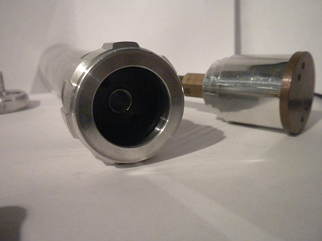
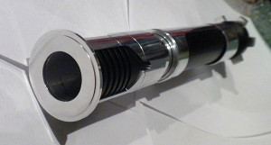
you get this:
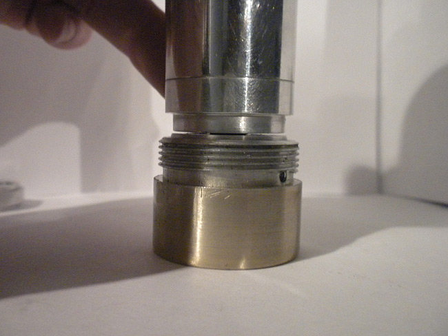
the speaker side.. (see how its threaded through)... maybe dab of glue too?
alternate pommel (still works)
off-topic:
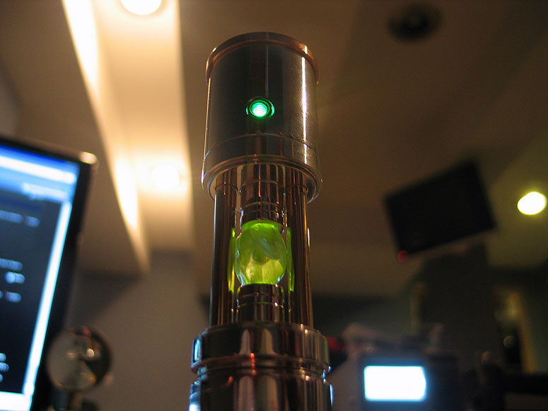
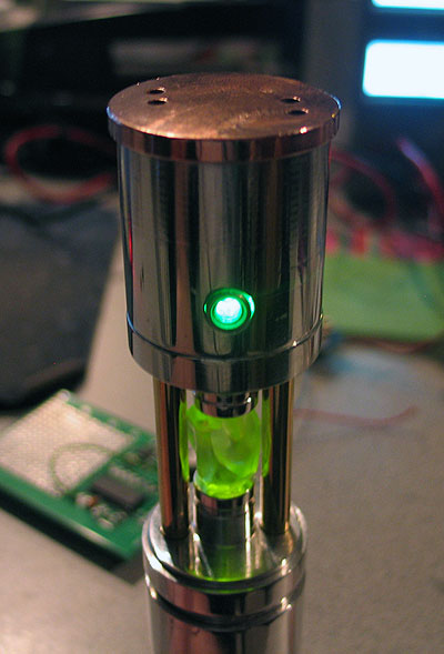
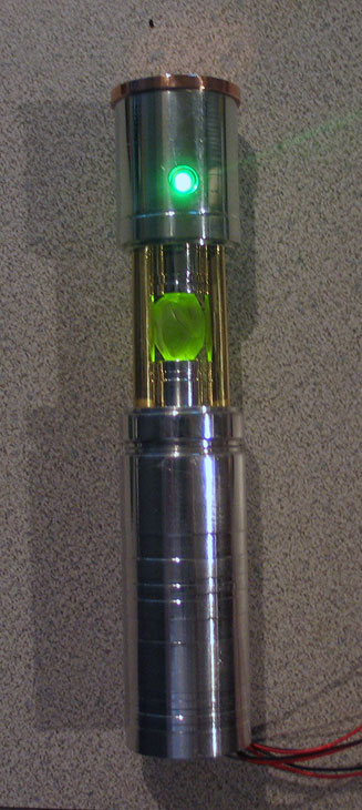
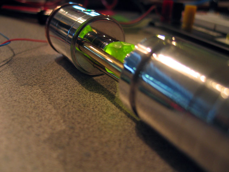
Here is the top portion.. (although a bit off topic)..notice similar 'stem/bearing' system..
but this time a top part goes over the bearing.. (set screw secured to bearing)..
and it spins the crystal, etc..
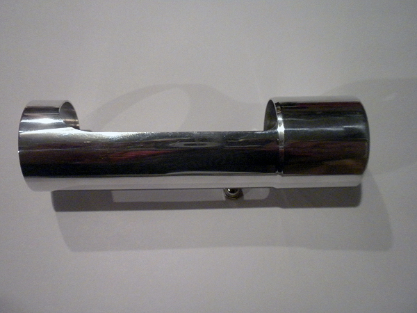
back on topic:
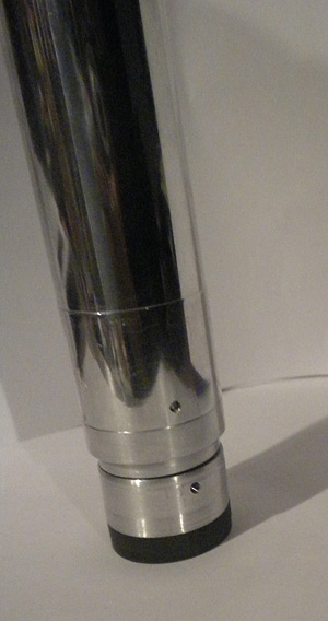
ok..so you take the whole thing..after you secure the 'bearing mount' to your core or chassis...etc..
and it slides into your pommel.
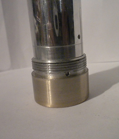
you can see the little drilled & tapped hole in the pommel.. un-obtrusive.. and it secure the pommel to the 'core'..make sure you secure it to the 'free spinning ring'.. and not the speaker mount..
side view:
feed back always appreciated,..
Im sure it can be improved upon...so thats why I shared it..LOL
maybe not for every build..but if the case calls for it..here is one solution to apply.
Thanks
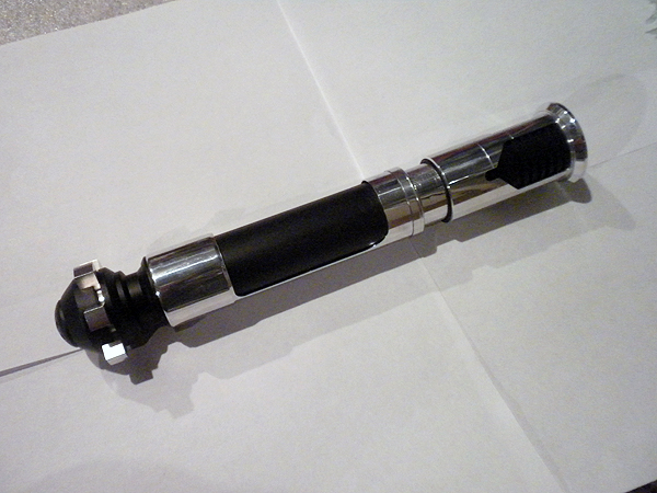
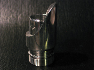
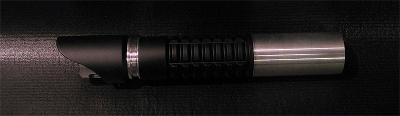
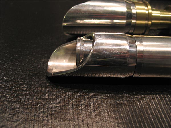
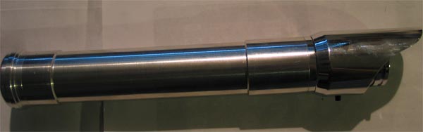
Custom/MHS OBI-TPM (hybrid)
ok..so this has been on the burner.. for....well for a long time actually.. I sorted started it when I saw Obi-Dar posted his build start...
it was shelved.. as I didnt care for the route I was taking at that moment....
anyways did some more work on it.. and here is where I am at.. figured Id get some feedback..
I think it looks a bit 'weird' to me because there are no cut-outs in the shroud/emitter yet..(Im hoping thats all it is!..lol)
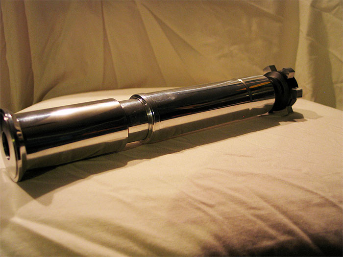
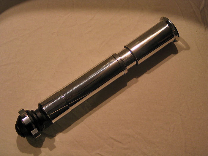
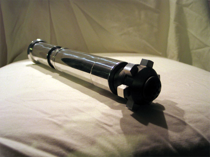
as far as being an 'exact dup' in dimensions.. its of course not.. (its no ACE OBI TPM to be sure, spot on with awesome machining) ![]() .. 'but'..its not that far off from the dimensions I got on-line.... the most notable place is the main hilt 'OD'.. which will mostly be cut away so I dont think it will have that much effect on the final look... every thing else is exact or a not 'too bad'...
.. 'but'..its not that far off from the dimensions I got on-line.... the most notable place is the main hilt 'OD'.. which will mostly be cut away so I dont think it will have that much effect on the final look... every thing else is exact or a not 'too bad'...
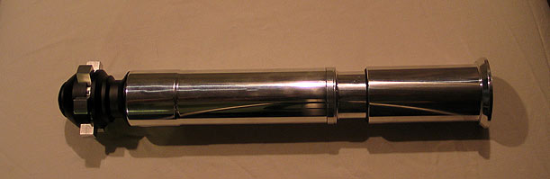
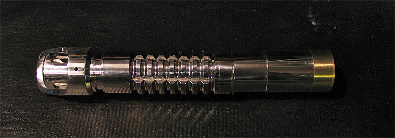
overall length is over 11".. but little under 11.5 if I recall..
feedback is appreciated of course. ![]() things/areas to work on.. (although its not complete of course).. or things that should be re-done perhaps?
things/areas to work on.. (although its not complete of course).. or things that should be re-done perhaps?
Thanks.
(Im no photographer!)
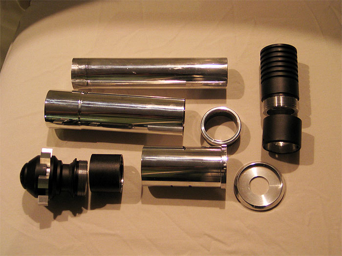
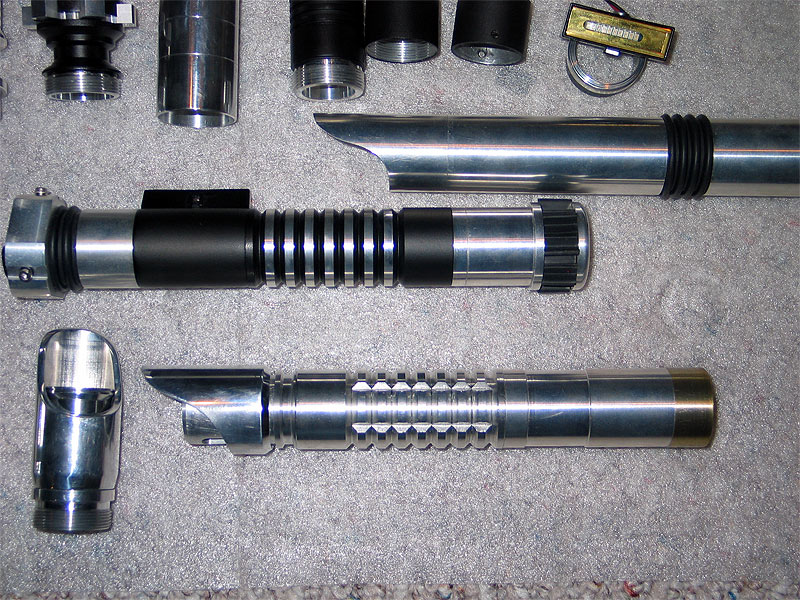
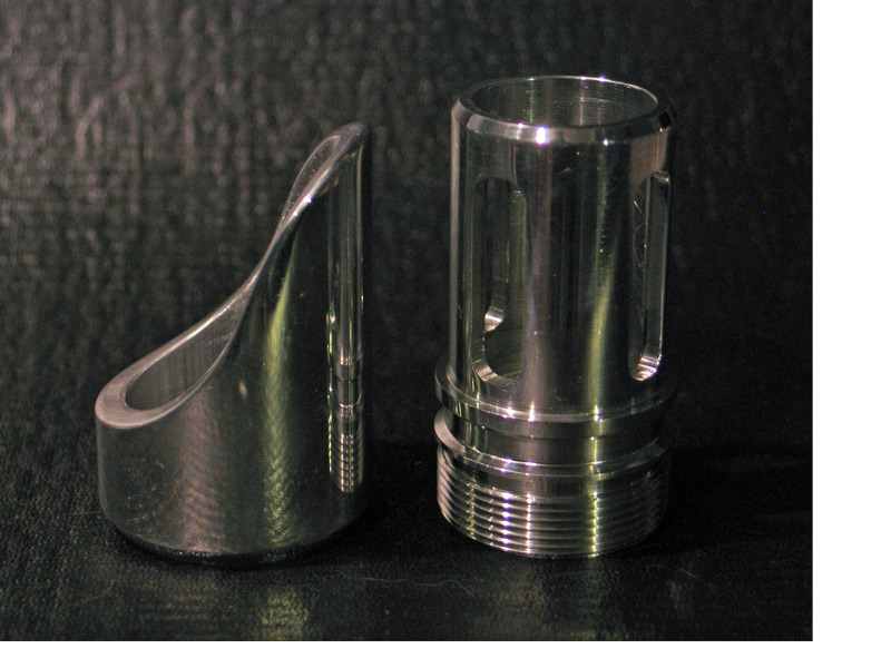
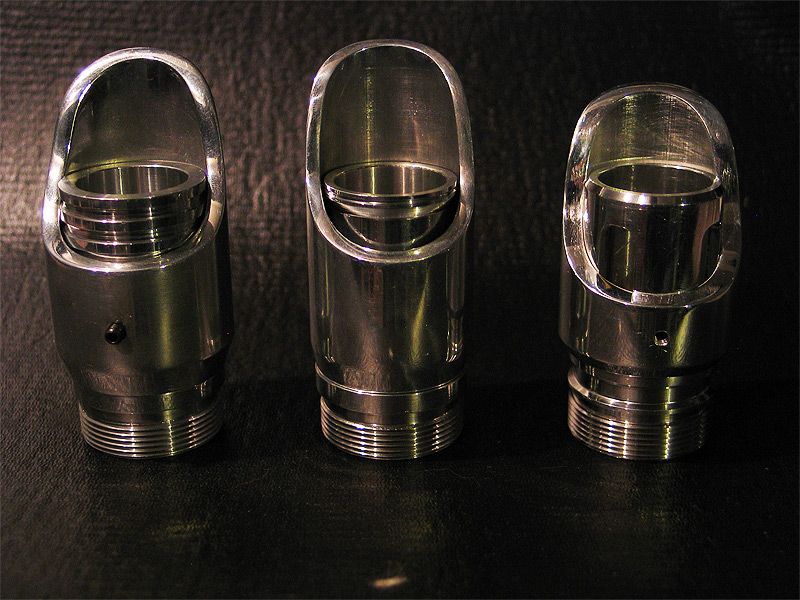
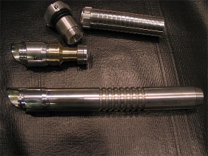
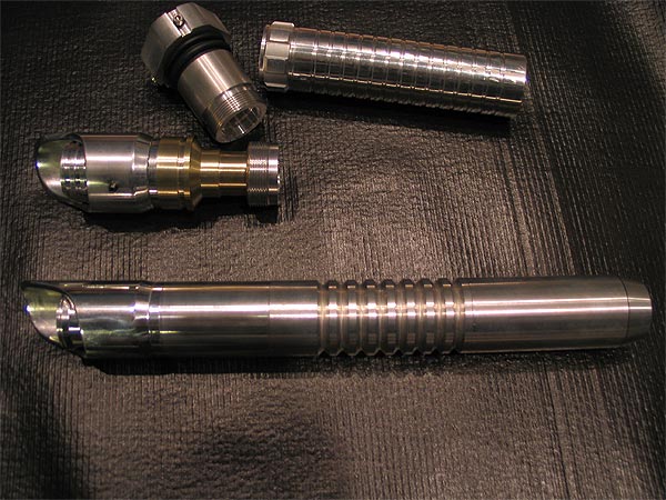
The parts used:
1 x Ace Obi TPM pommel
2 x 1.5 sink tube adapters (turned down to be 1.39 OD and faced to be roughly over 1")
1 x 1.25 'core' aluminum tube so it has a 1.25 choke section ![]() (slightly modified to meet ID of one of the adapters I used)
(slightly modified to meet ID of one of the adapters I used)
1 x MHS BH #3 turned down to be 1.39 OD)
1 x custom hilt shroud ID bored to 1.39...OD to match the TPM as best I could..
1 x custom shroud ring/support for the top end which has a bit larger OD and design
1 x custom emitter shroud ID bored to 1.39 (OD has a bit of a lip/larger OD than the rest for the 'top ring")
1 x custom 'ring' taking a cue from Randy/Obi-Dar's build of course.. (and because I fubar'd my 1 piece attempt the first go-around) (DOH!) :dft001:
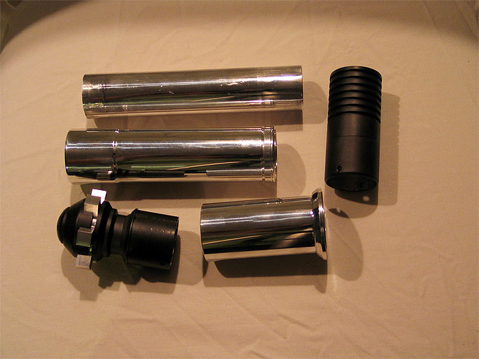
All parts
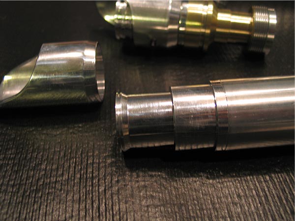
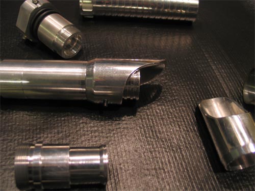
Rings attached:
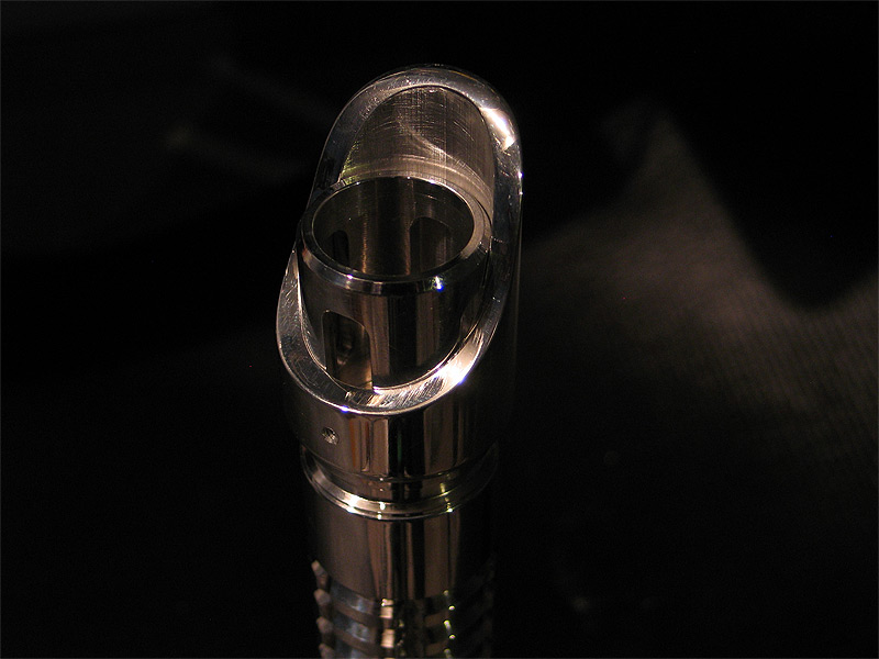
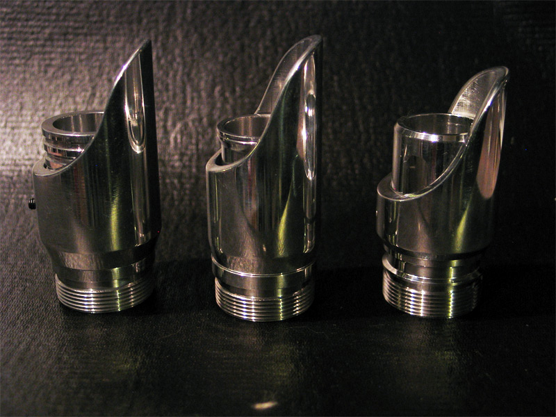
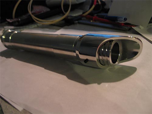
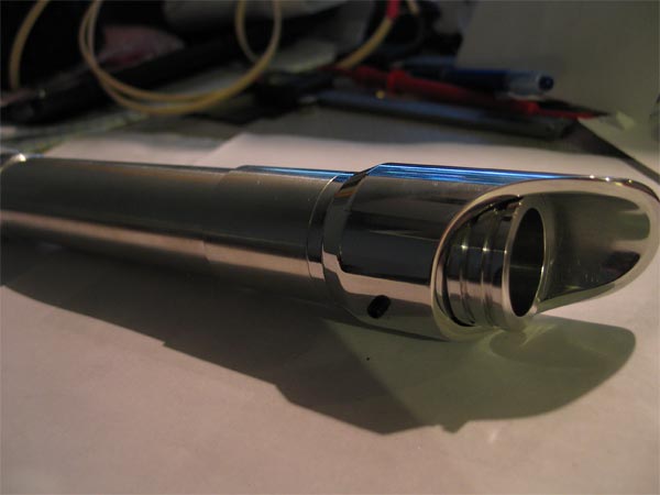
Top section:
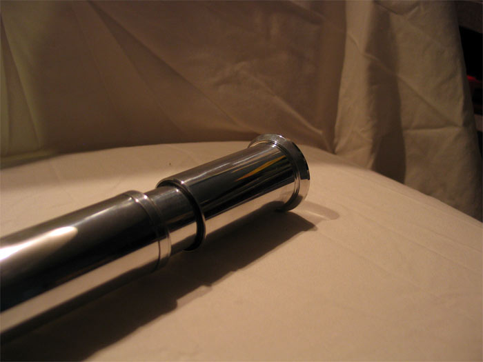
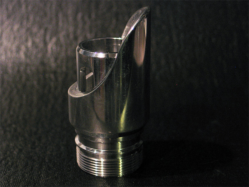
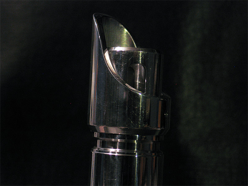
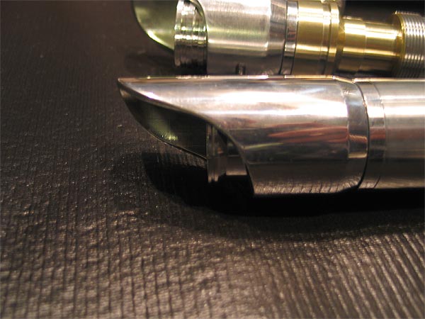
Side:
Angle:
Full:
Last:
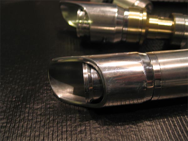
The OD of the ring needs to be opened up to 1" to accept a blade still.. but thats really only about 10 minutes of work to do..
if it passes the test(s).. then I'll work on the shrouds or something.. wire it up.. and see what board it gets (if any)..
if it goes over well.. I always have the 'rule of two' for builds.. and there is parts to make another ![]()
Thanks gang.
-------------------------[update II]------------------------------------
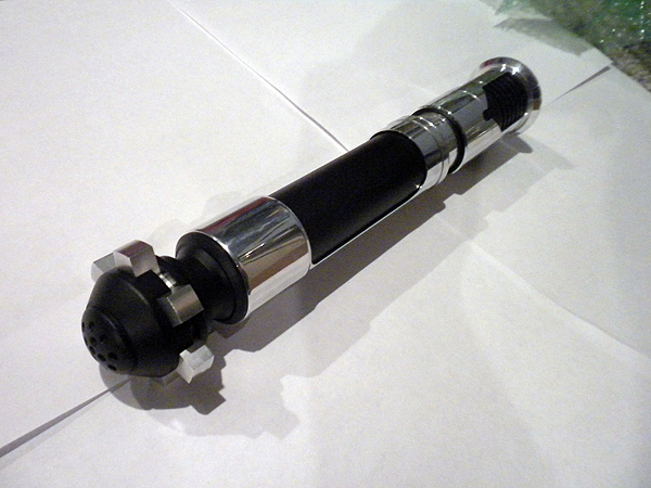
just some quick update shots:
got the 3 windows in the top emitter shroud and the window in the grip shroud cut out by Tim (great work too, thanks Tim)
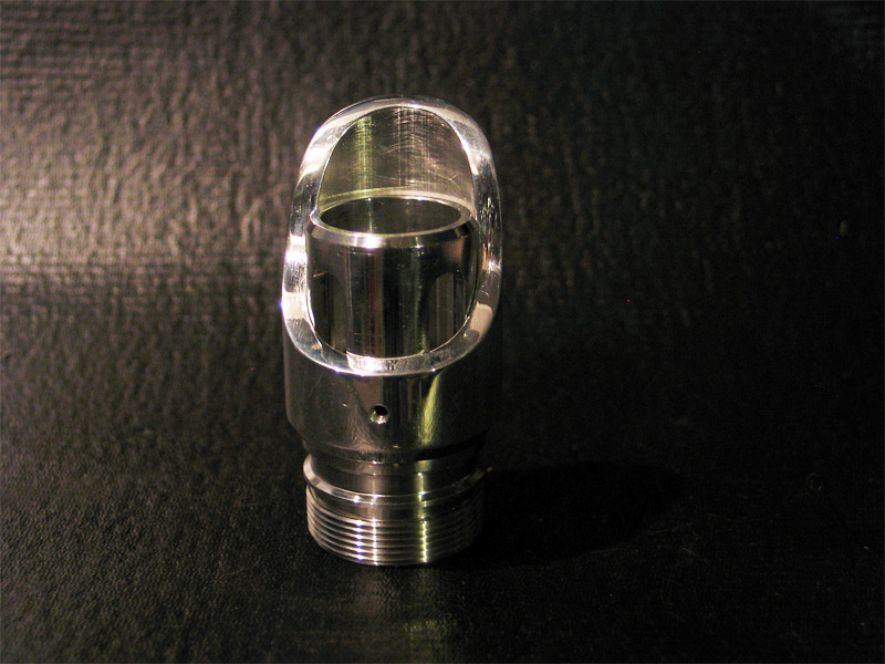
bike value
some bezels
and the delrin 'grip section' and I can focus on internals..
not sure if it will be than board/battery pack etc...
not too much room for a chassis!
some pics.
(I think she is turning out very nice.. no "Erik/Ace" version!..lol.. but nice to me!) and not too fat/chubby.
the shroud and BH fit like a glove.... and Tim's window cutout make it look so nice.
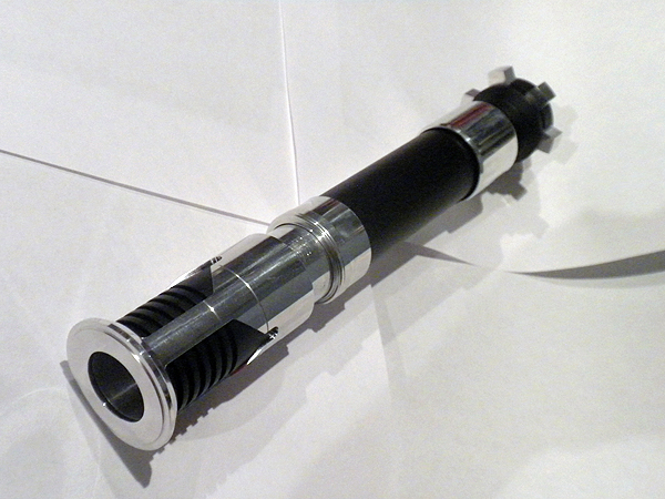
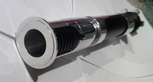
I put the lines/grooves in just about the perfect spot with the BH and the modified adapter 'seam' makes it less noticeable
Heres a pic with the ring on and all together.. (pic isnt so great..its look nice in person.)
more pics of the sleeve I turned down..with slight dip/bevel that i sent to Tim to be cut out.
A pic with the sleeve and the 'collar/ring' for the 1.25 inner and sleeve connector/support. (this part is being re-done for better tolerance fit....that god its not a hard part at all!..)
Some side/full length views:
no delrin inner grip section.. just a 'temp' all black filler...lol
hopefully I'll get some free time to wrap up the hilt stuff.
Thanks
xCore: #2 (Green Lantern) aka: Eastern57 x-mas gift
Eastern xmas gift (copy of same proto system above)
I have a couple more variations on the modular sections/parts..
appreciate all feedback...
specifically on things like:
switch mount/bucket
*standalone vs. part of heatsink bucket
*generic enough for all switch types or maybe 2-3 yes?
battery/sound/speaker bucket:
*size constraints? stuffed 2xAA sized batts and a US2.5 in there.. probably some room for wires..not much else? (not sure of CF would fit due to height.. maybe different battery solution?)
*make both speaker only bucket and attach battery/sound board to 'rods'? or other area? and the speaker/battery/sound bucket? or just the former/later? (maybe milling out some grooves in the bucket will help with space a bit?
heatisnk/led bucket:
*right now the led/heatisnk is part of the 'core'.. should it not be? shoudl there be an alternate 'modular' section you can choose as an 'end cap' to the core?..and then you just run wires from core to led, like in any other normal build?.. of course you would have to choose to either lock/secure the core using the speaker mount end 9liek in normal MHS builds using a pommel speaker mount...or an end cap/section that has the OD of the heatisnk..and using that approach to locking/securing the core to the hilt?
Eastern will be giving a review of his as well when he gets some time to play with it.... maybe covering some of the topics above .
Thanks
Custom MHS BH #3:
I posted asking a few questions on PC'ing..
this was inspired a while back from Big EZ's Tactile build.. (which seems to have been a trend lately)... but was supposed to have a 'trigger guard' built in..
it does.. but Im not 100% happy with it.. (taken from a toy gun from my kids).. looks 'ok' after paint (maybe better)..
I have one more guard I wanna try (hoping it will fit better or a mount solution will reveal itself to me!)
anyways..
here are some pics of the WIP build..
modified BH
custom shroud
v-groove
3" extension (modified)
stock MHS pommel
I also fubar'd my 3" extension.. (pics below)..LOL
so I need to grab another off the bench and mod it again.... goes to show.. do NOT PUSH the amount you can turn down an MHS part! (especially by the threads!)
anyways.. figured Id post a few pics.. and what NOT to do to your MHS parts! LOL.
before I messed up the 3" extension:
Broken piece in place:
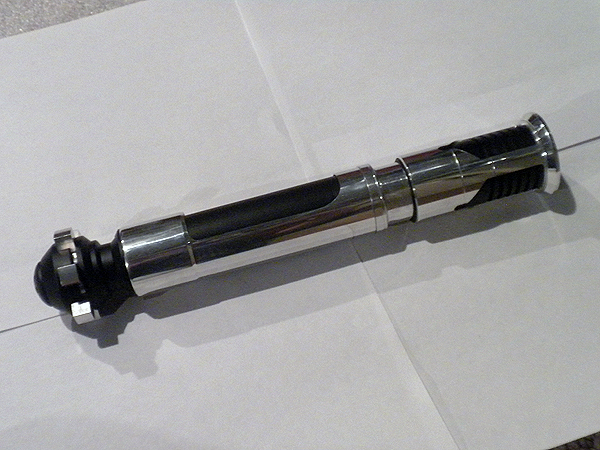
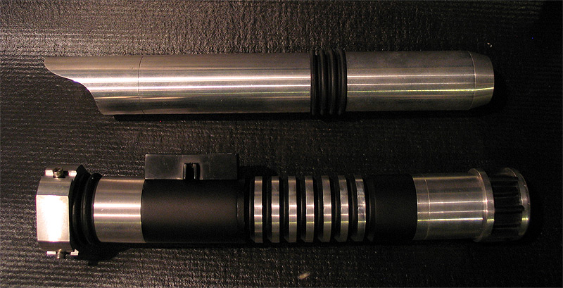
all three mod'd BH's with custom shrouds (3 so far...and I think last..I have 3 'longer' versions that are similar to a 'graflex' top in length (not quite) that go over not only the BH's..but part of the main body as well..... too bad it'll be seen as a rip of Slothfurnace graflex build that uses it...cause the firstone is very similar.
some other junk too.. my first red/sith build (bottom)
and an attempt to make a 'clean'.. future'ish saber.. very clean..nothing but liquid chrome 'look'.. (working on the MC type buttons..but a bit more 'recessed'
and my mistake: =(
any thoughts or ides on the trigger/guard is appreciated.. Im really NOT digging using plastic or salvaged from a toy.... but not sure what else?
-----------------------------------------------------------------------------
I PC'd it..
as well as the v-groove..
still on the fence
1.) do I remove the PC from the 'ribs/nubs' on the v-groove? (and pc them trans gold?)
2.) do I do everything that is in bare aluminum in trans gold? (nubs and BH..and pommel)
keep in mind the 3" exntension is there as a filler..cause the other one broke.. needs to be turned down still.. and some visual mods/grooves added..
that will also be black.
suggestions on 1 & 2?
sorry only one pic ATM... the others were kaka..
Custom MHS BH #2:
my second attempt for a shroud was to make one NOT so bulbous/wide.... (but after having that fatter one..and seeing the newer 'skinnier' one that isnt NOT much wider than stock MHS width... I doubt I'll do anything else BUT the fatter ones now..they just look and feel so much 'nicer'.)
figured Id post some pics of this second see what you guys think..
these BOTH utilized OLD BH's I had on my bench that had been used for mock ups..sizing..etc..and had been pretty beat up..and useless.. until they were used in this shroud/revamp project..
the other one used a BH#3.. this one uses a BH#1 that was modified a bit like a graflex holder..(in my mind) lol
feedback appreciated.. love it...hate it... (pack it up and go home douche` bag!.. whatever ya got!) =)
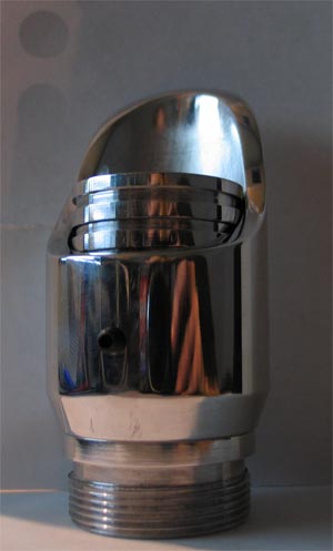
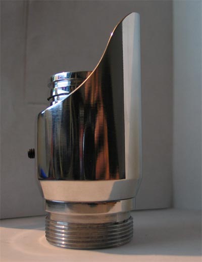
pic of base BH now:
with shroud (front)
side:
side 2:
compare shit to it on a random hilt ..and next to the other one for size check:
Custom MHS BH #1:

Hey gang-
Cut the lawn today... and while my boys discovered the game 'kick the can' (LOL).. I got a couple hours in the garage today! (woot)
(man..without a mill this kind of stuff is a PITA!) lol
I had mentioned this long ago as an option in the TCSS store.. (shrouds, overlays..etc).. generic enough to customize/spice up ones saber
(before Tim had CNC milling etc..etc)
figured Id give my had at one.. (I recommend using a thinning wall tube than I did!) haha
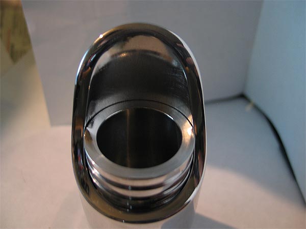
anyways.. tell me what ya think.. I turned down an MHS bladeholder.. and bored out my stock to match..
then turned down the OD to what I felt looked/felt 'ok'...
the "S"-curve was done by hand..bandsaw, sander...files.. (buffer)...yadda yadda..
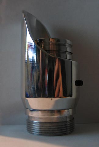
and what it looks like on a hilt..
feedback is appreciated..
thanks guys..