Illuminated Switches: (tiny)
OK.. I talked to the vendor off & on a few times.. and basically for a higher price (and if they are in stock).. he will mix-n-match some switches (led colors) and caps for me:
to re-cap:
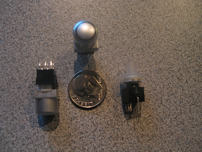
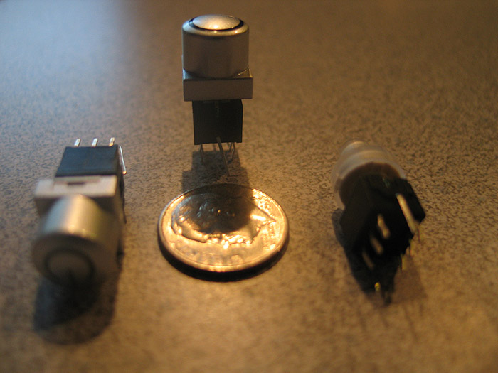
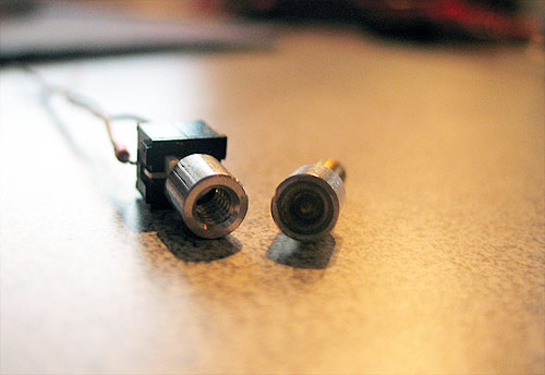
pics of the sample switches they sent me..
according to the spec sheet:
http://www.rjselectronics.com/PDF/PB613x.pdf
page 2 of 5
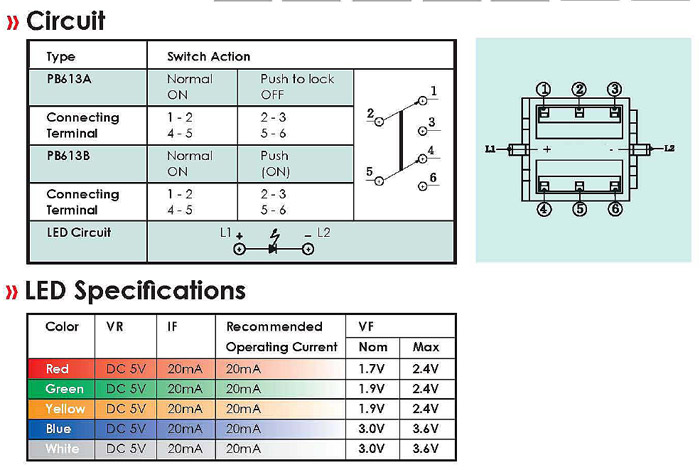
it says Switch Action/terminals
Normal ON:
1-2
4-5
Push to Lock/Off
2-3
5-6
the pics are little 'distorted' because of either my shaky hands.. or taking a pic of the LED lit up..
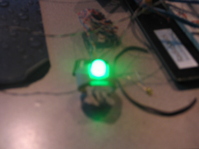
1.) I took all the silver paint off the cap..so the whole thing lights up.. (pretty sick).. tip: to NOT leave the soft plastic/rubber base in while doing it
2.) the second is the default cap with the ring in it.
using the same mounted base.. Im not sure what other colors I got in the 'samples'..
RING:
SOLID:
what we have available to us is:
COLORS:
RED
GREEN
YELLOW
BLUE
CAPS:
BLACK
SILVER
I only asked about getting the RING style (as pictured) but in black and silver (silver is pictured)
If there is enough interest.. I will try to scrounge up the rest of the loot to get an order..
Im thinking they will go for about $5 each shipped..
let me know.
Thanks
------------------------------------ [part II]--------------------------------------------
I had made comment about it previously..and am just now getting around to posting the pics I took of these..
My first attempt at using (mounting) these was much along an early Jay-Gon approach using a PVC 'ring' or semi-ring that could 'flex'.. but that solution left things very close to being a 'one way' switch install without potential damage...
so I began to think about alternate ways to mount these (or other difficult mounting switches)..
when I saw Erv's post about modifying the CAPS.. it reminded me to post what i came up with.
Ervs way of modifying the caps is awesome.. (I'll be doing a few like that for sure).. but not everyone has access to a lathe like we do....
it also leaves you stuck with the having a cap style of choice with the bottom ready to 'snap' to the switches stem..
my approach sorta gives you more room to be able to utilize different (metal, ala Madcow) style switch caps for example.
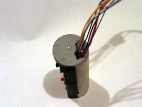
my first prototype was made from not wanting to waste such a small DPDT latching type switch..(just because I had blown the LEDS in 2-3 of them..)..ssshhhh
Something that could fit and be easily mounted inside (1.25 ID) a hilt of a normal MHS section..
and also allow for easy cap fitting from the outside.. (like Erv showed on modifying the cap OD)
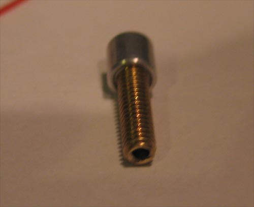
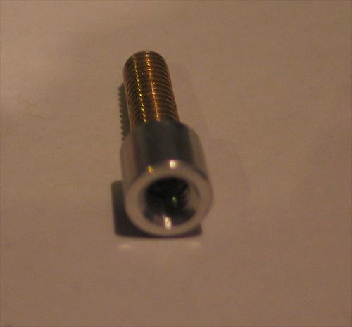
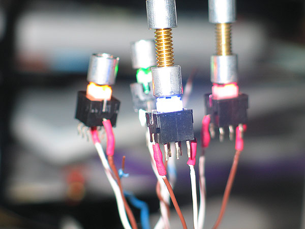
I also took it one step further...and drilled out the stem on one of the thumbscrews so I can mount any type of head I want on it.. (even one with epoxy in it, similar to the screws that let light show through)
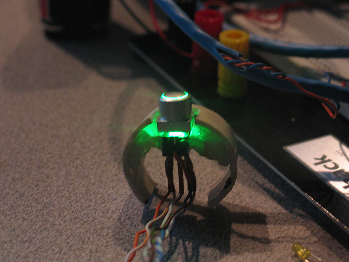
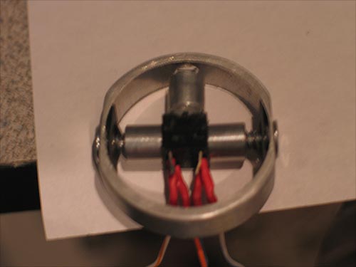
its basically a section/ring of 1.25 OD aluminum tubing...with some screws and speed nuts..etc.. with some thread aluminum spaces.. everything can be purchased at Ace Hardware or the like..for a couple bucks..tops.
might throw a dab of hot glue over it just to make sure it doesnt loosen up..but its been very stable so far..thrown all over the place..for weeks now..
I'll get the rest of the pics up, of the threaded stem being illuminated..
(I just need to put he dab of epoxy or something in the tube to diffuse the light more..)
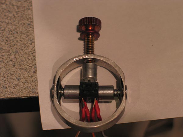
the last pic is where the dab of epoxy will go..
Im hoping it will look like an illuminated, metal 'Madcom' style switch.
the cool thing is..with this 'ring' type set-up.... (much like my approach to chassis' and crystal chambers...etc) it utilizes the pre-built MHS 'feature' of the space in the threads... and to lock down the ring..
this one in the picture fits (tightly) in a 2" section.. in the space left over by the HEATSINK drop down...and having one of my chassis 'disks' locked in by male threads on the other end..
so whats that? a little over 1/4 inch or so?
not 'precision' made, (Im sure others could made a better looking one)...but its not too bad..and you dont need anything fancy... drill/drill press and maybe a sander to grind the sides flat.
feedback? thoughts? improvements?
I'll get some of the illuminated ones posted...
anyone have a suggestion on what to fill the top with first? (epoxy/hot glue)?
---------------------------------------------------------------------------------------------------------
Yeah..looks a little more 'technical'.. and isnt an eye sore in a build..
I have even integrated this 'ring' section into one of my chassis disks (so its all one piece of aluminum)..
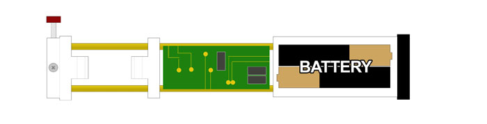
so the chassis disk 'portion' gets sandwiched between the male threads and the internal threading 'lip'..and this switch mounting 'section' is after that (still all one piece of aluminum..just turned down a bit for the OD to fit the ID.). ![]()
this diagram might help..
Heavy dueling? I guess I couldnt say.. "I"personally dont duel..
but they are fairly sturdy.. I mean Ive thrown what you seen in the picks around..at walls.. dropped it.. nothing ever moved or popped out of place..
but as I said.. I'll probably just throw a dab of hot glue in the corners to secure it more so nothing gets un-threaded or anything..
but how much 'pressure' you think it'll have on it? and from where? (what point?)
depending on how you implement this type of approach in your project..
(unless the rest of your 'guts' are free floating and sliding all around).. Id say this 'option' whether it be part of another 'disk/section' locked down, or its own ring not secured by anything expect the 'threaded post' of the switch will function & hold up well.
thanks for the looks and comments.. hope someone finds it useful..
---------------------------------------------------------------------------------------------------------
I dont think I ever really posted these images (in public at least) haha..
these are sorta old.. (about the time when I first found these switches and got some samples..and was left with mounting quandaries) ..at the time I was altering a JGJ approach I had seen in some build thread or something..
BEFORE I started working on the 'modular chassis disk' business.....(which is a much nicer looking and more versatile system) haha ![]()
I used what I had available and much of it was hardware stuff..pvc/plastic.
I still find these regular golf club protectors/tubes to be GREAT for chassis building.... and I have used them a few times in the past for stuff..
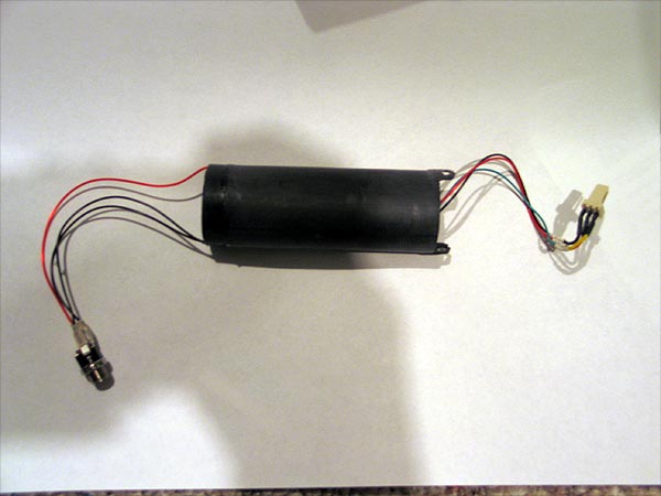
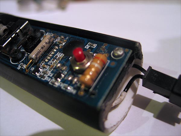
I have my 4.8v Nihm battery pack (the one that TCSS used to sell a while back).. and a speaker mount..
the project this was for has a pommel mount recharge port:
filed 'channels' into the speaker mount so I could run wires past it to the pommel for the RCP..
other end had a 3 wire connector (GND, V++ and speaker) to connect to other sections..
(these innards are very modular themselves)..
battery/speaker section
switch section
sound/driver board section
**legs/ladders on the ends with holes in them..as that is where the switch ring mounts/connects to that piece (very rigid)
soundboard/driver board:
using part of PCV and old 616 mount..
I have, the 616, Plecter dimmer, 2 clash sensors.. (before we did bulk order..thanks AK)..
I think I studied with Eastern to get some cram-fu lessons in this thing (**bonus pic at end)
use the top/lid of film canister to make a 'cap' so to speak so nothiner metal would short out on the switch mount ring/chassis
all 3 section together get me this:
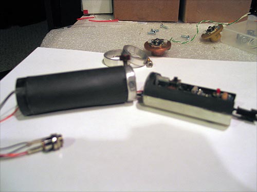
all of it fit inside MHS ID.. the the speaker sanded to press fit and it 'tight' and secure..
its nice little core... nothing fancy since its plastic and a little hot glue in places..
here is a pic of the ring mounted in the battery/speaker section..
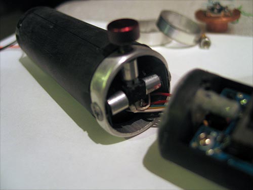
wires are tight & clean... (I could have probably shortend some of these in hind site to make fit easier).. every is of course heatshrinked and everything is in male/female connectors..
switch has connector (so it can be serviced)
speaker/battery section has connector
led is of course quick connect as well...
for bonus points..
I solders a clash sensor to plecter dimmer for the flicker effect on clash (needs fairly fresh batteries to see it well)
I also soldered a momentary switch to the plecter dimmer board so you can access the menu and change the flicker effect, ramp up/down times..etc..
and mounted it in the 616 board.. looks nice..
no wires seen on top.. so if you want to switch the sound font to be jedi or sith..you can also use the momentary button to access/set the dimmer options as well
these switches.. are 'very cool' IMHO.. and being illuminated shows even more possibles.. (watch for 'custom' illuminated switch heads post soon)
I think these way of mounting is VERY practical..
why?
it can be done by any/everyone with or without a lathe.. 1.25 OD tube.. a tube cutter.. a drill/drill press.. and a sander
it can be incorporated into other 'sections' of a chassis fairly easy..
when you see the version that is incorporated into the modular chassis disk it makes it 'all' look so nice and professional.. instead of a nice chassis.. (made out of whatever).. and then some button/switch hot glued or wires running long was down the chassis..
anyways..hope you all like..and it helps others mount these switches (or anything for that matter.. tiny recharge port of Easterns for example..) (hint hint)
--------------------------------------------------------------------------------------------------------------------
wrap this thread up..
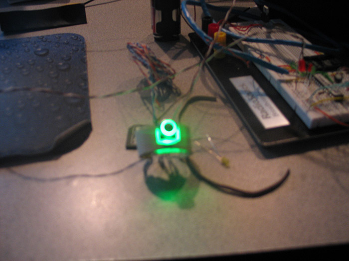
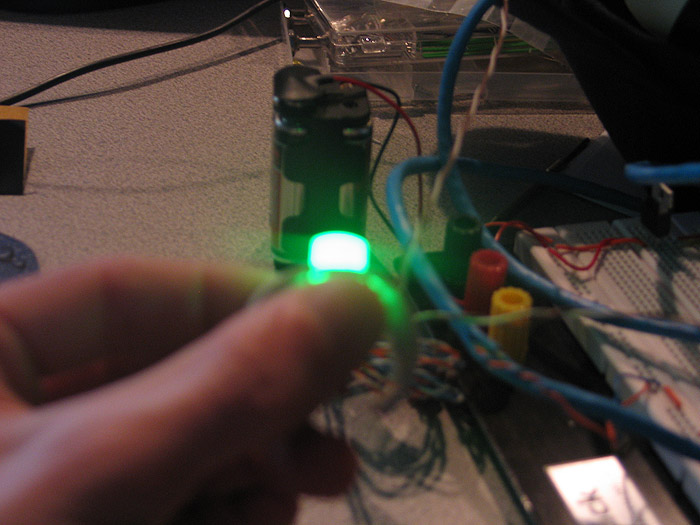
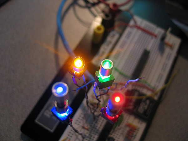
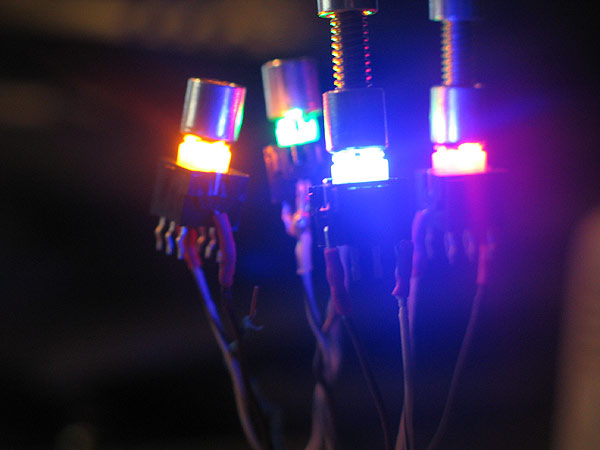
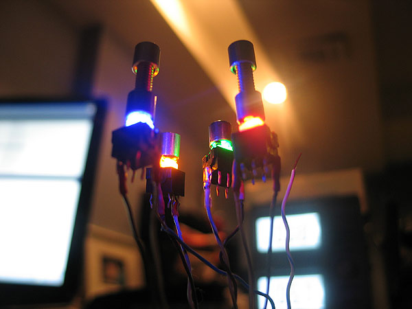
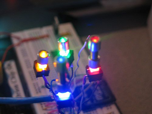
here are some of the pics of the switches and the colors of the LEDs (while on)..
you can see the style of caps Ive been using/making to:
1.) deal with easier mounting
2.) still utilize the illuminated/led option of the switches.
these have hot glue in the caps to diffuse the light.. (its too 'clear', something more 'foggy' is needed to diffuse better)
(I also think the small 'hole' in the threaded stem limits maximum illumination as well..)
I have another pic (cant find where I saved it!?) haha.. showing how 'low profile' you can get with alternate cap/heads (like a metal thumb screw)
I think either turn down the stock caps OD/base on a lathe..or making a custom stem/cap combo is he best way to go for these...
with the aluminum 'heads/caps' picture above.. you can actually almost 'flush mount' them depending on the 'ring width' on where internally it is mounted in your part.
later...
------------------------------------------------------------------------------------
update: thanks to tip provided by 'erv', these switches can be both (default) latching.. and after a mod can also be a momentary switch! great tip! and makes these even MORE useful.