PoC: Plunger Switch Prototype

I never posted these... and just recently remembered about them when reading Ace's Obi TPM run thread.
I posted on them..(did a quick sketch while at work to help explain it).. to maybe offer help.. (but no one even acknowledged I posted... boo hoo.. poor me.. right?!) ![]()
![]() lmao!
lmao!
Erv drove into me 'document everything'.. (so here I am.. maybe it'll help fix a cram-fu problem!)
anyways.
I worked on a few different ideas of 'mechanical' switches or methods to trigger latching/momentary switches when I got those illuminated switches a while back..and then again when I started working on 'cores' and all components secure to it (ie: Easterns x-mas gift/x-core..integrated switch)
(Im sure you've seen a few here and there..but I dont think these plunger style ones ever)..
I suppose it depends on your specific application/project but (again) the idea is sound/stable..
yanking the pic I made in Ace's Obi run thread..
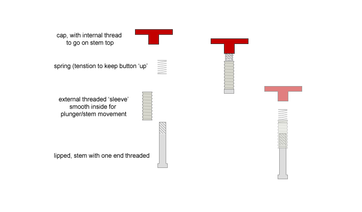
for myself,.. these were to serve several purposes.. solvable by either changing the length of the outer threaded sleeve, the length of the 'plunger'...or both. =)
a shorter length threaded outer sleeve lets you thread directly into the hilt...(for switches that are very close to the top of the hilt)
a longer length threaded outer sleeve lets me thread into the hilt..but ALSO my core (or delrin disk..etc)
when I do this..I need a longer plunger end as the switch is usually set deeper and not at the top by hilt/hole.
these are all garage/hacked, home machined..etc Im sure if Ace tackled this, they would turn out much nicer,,and the fit and finish of course would be top notch. (even maybe a lip or something to stop screwing all the way in)
only con I have found so far is its a bit difficult to screw in the threaded sleeve sometimes.. (you need to tape up some needle nose pliers and get to turnin'!) lol
(this is actually how I am planning on finishing my own personal Obi hilt using the bike vale and red button as my switches) (one of these days, right?) ![]()
![]()
ok just so there is some Proof in the puddin',..another proof of concept..(PoC)
some pics:
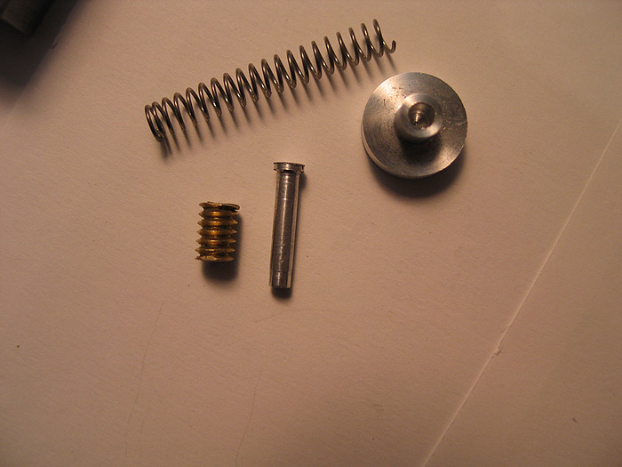
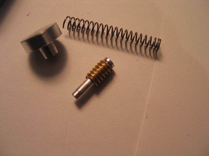
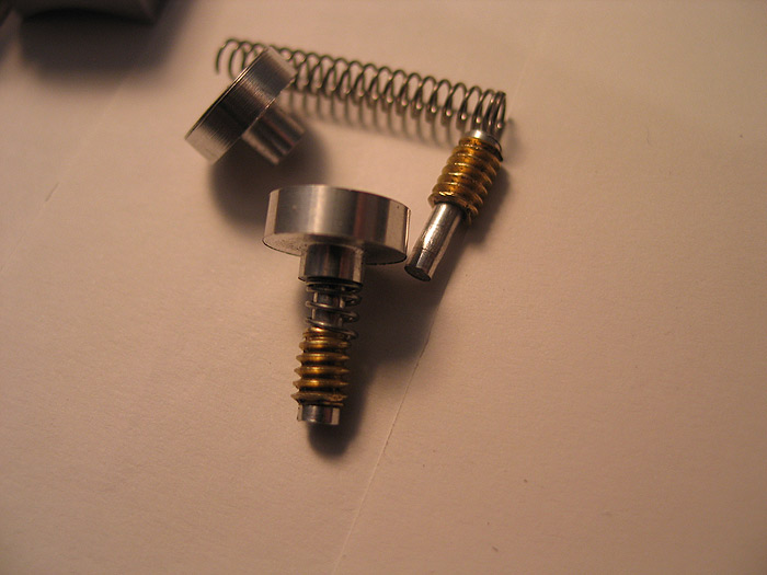
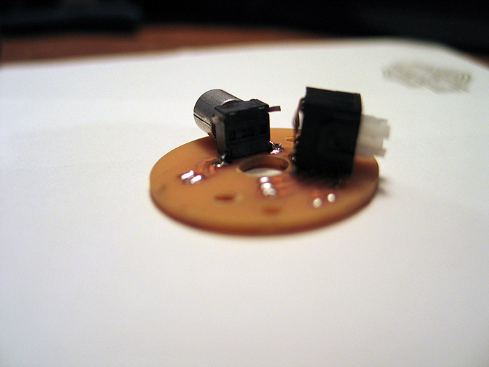
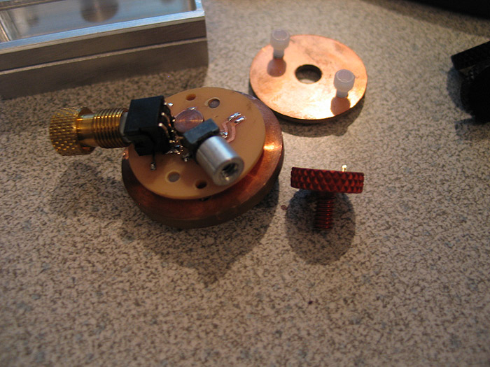
part(s) breakdown:
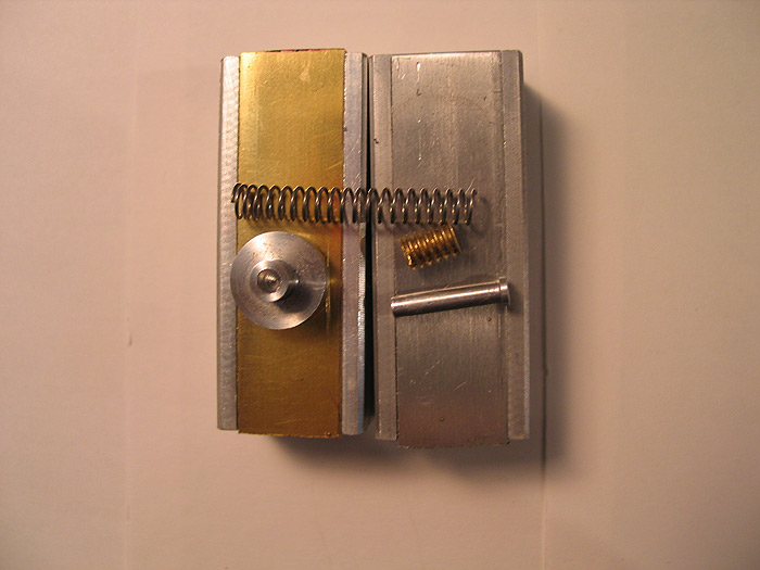
(on top of some TCSS boxes..with some brass and aluminum strips I cut out..same thickness..they turned out good..need to sand edges..and buff)
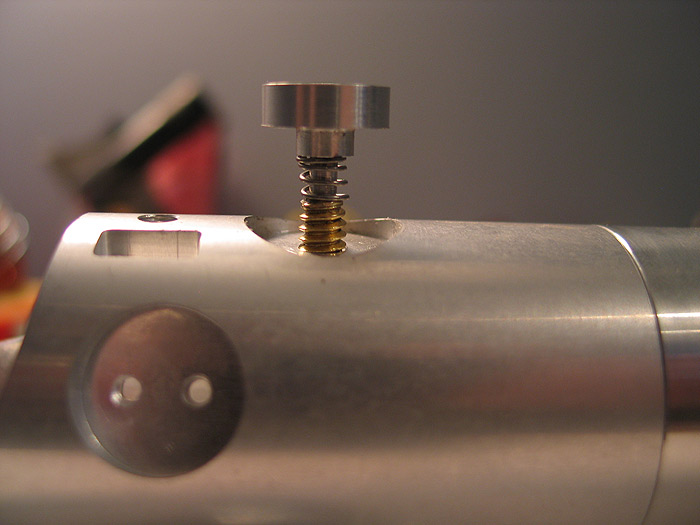
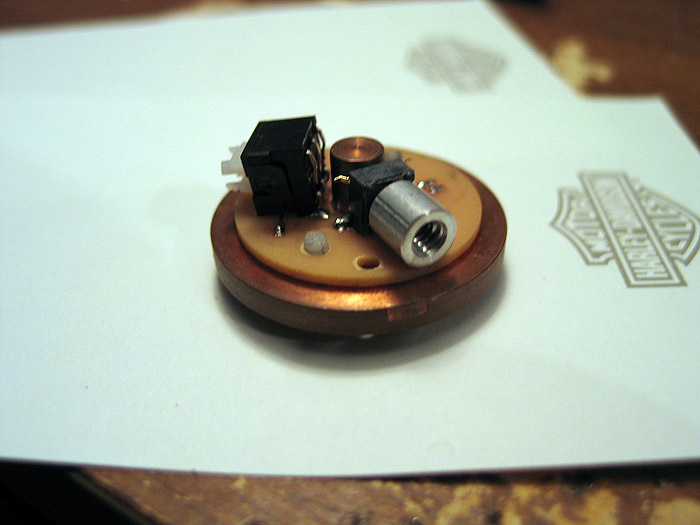
this is NOT fully screwed in.. but it is also a longer sleeve version.. cut the sleeve in half..
and you can even counter sink/bore the switch end to get it lower/closer to the hilt if you wanted.

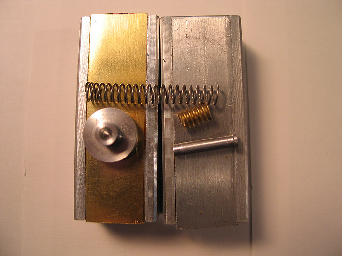
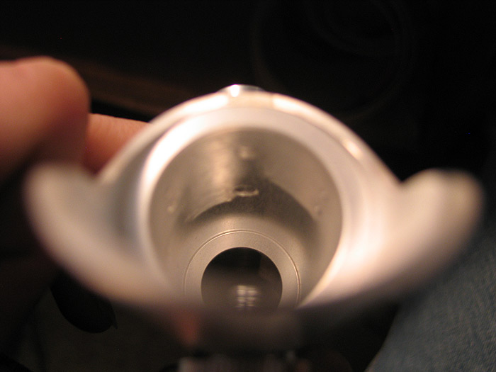
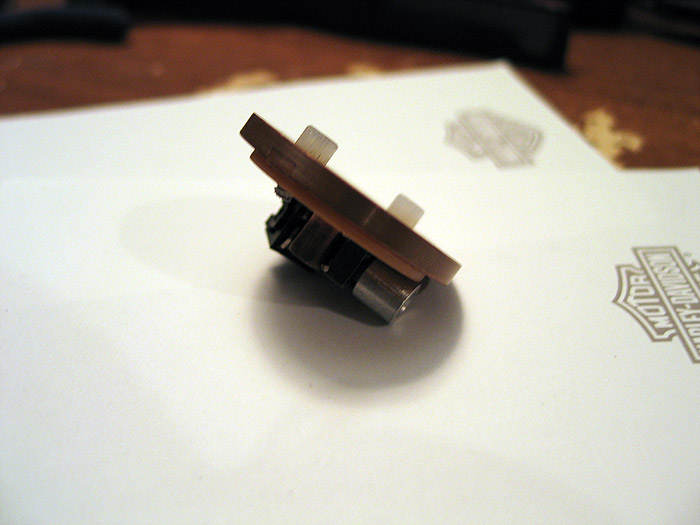
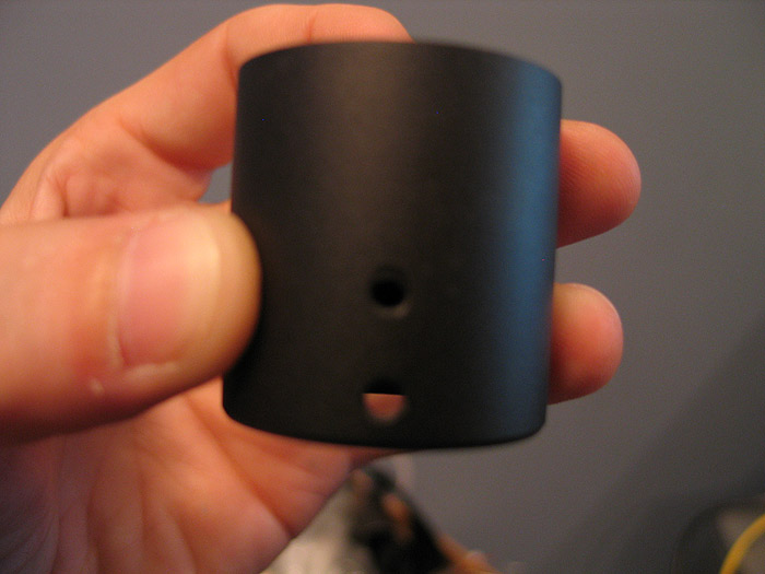
see how it works/side view:
shorter plunger see how it goes into hilt to trigger your switch.. of course these are changeable to any length to fit the depth needed.
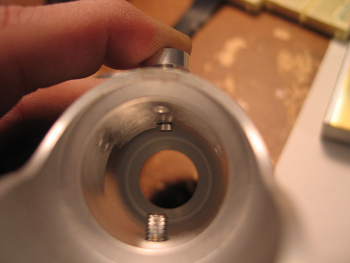
and not-engaged:
I have two more that are going to go on top of one of these control box.so the switches are on top of the 'cover' and spring like this.
anyways..hope 'someone' enjoys them.. LOL
thanks
PoC: Custom MHS heatsink pcb (for my Obi TPM)
was going to post this in the 'idea thread'.. but figured just make its own thread for it..
another step in my OBI TPM saga.. lol
trying to keep the size as accurate as 'I' can, and still having it be somewhat MHS based at the core...
I was stuck on finding out a way to use the stock switches as real, functioning switches for my hilt.
(Ive always been keen on the all-in-one core ideas... but have the switches on/in the core and some sort of cap/plunger on the outside has always been a PITA for me... here and there a few ideas have came out/been used)
for the OBI.. when everything was done,.. the switch holes would go (more or less) at the same exact level of the MHS heatsink.. so I need to adjust that a bit.. and also find a way to mount some switches in that area..
I had mulled over Madcows switch approach. but just wasnt a good fit..
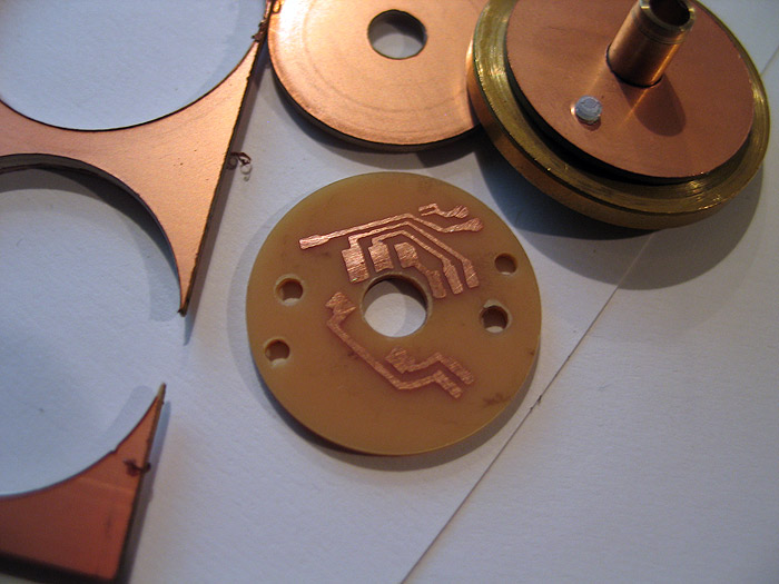
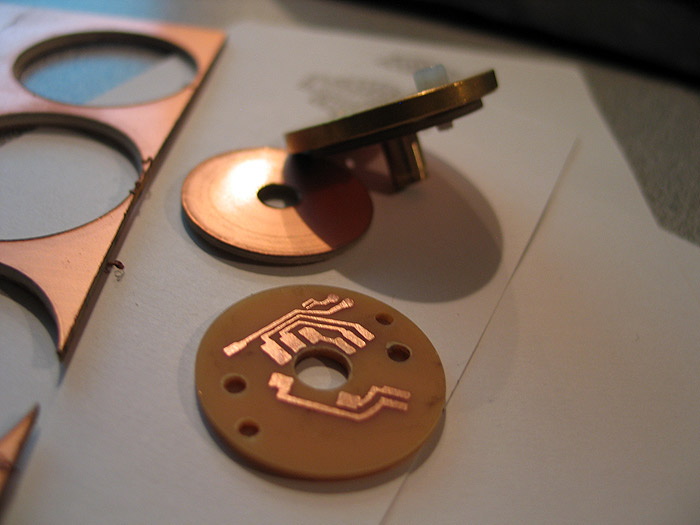
so I came up with a custom, round PCB, that mounts to the underside of the heatsink..and is secured using the same nylon screws that hold our luxeon star pcbs. (MHS hack!)
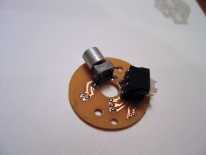
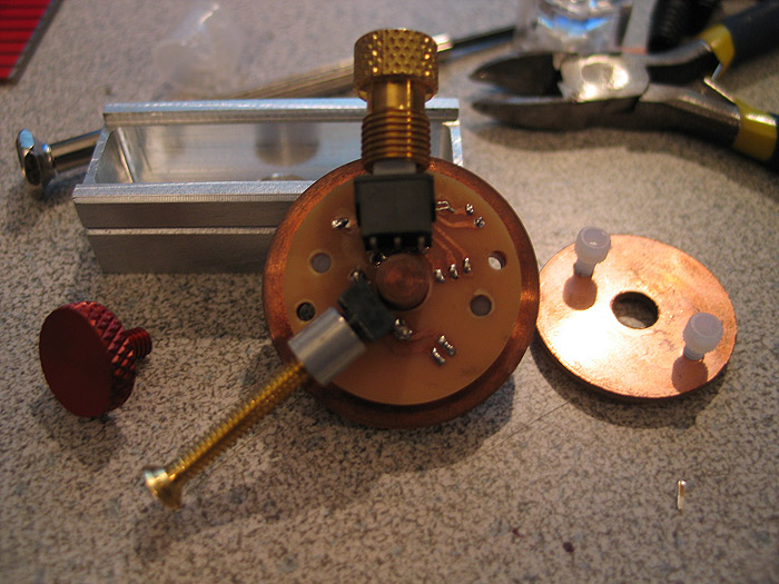
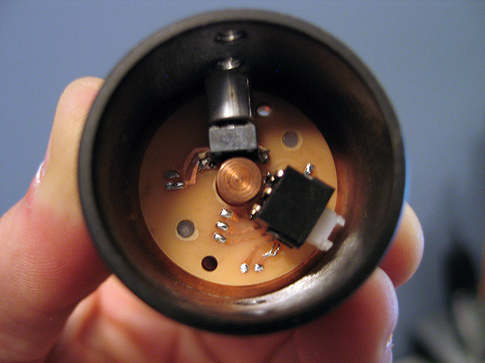
here is my prototype..
the bike valve switch will have an SMD led in it.. (like they normally do).. to light up the purple gem in the valve end. I just didnt put it back in yet..from doing the momentary mod to the switch (latching by default)
I also didnt clip the extra leads from the switches yet.. but I believe the idea is sound.. and can open up the doors for others to use the same idea/approach.. (nned to mount a unique switch?.. make a pcb for it!)
I posted a tut on how to etch your own pcbs..etc.. using your home laser printer and photopaper..
1.) make pcb deisgn in photoshop..
2.) print to photo paper
3.) iron to your copper clad board.
you get this:
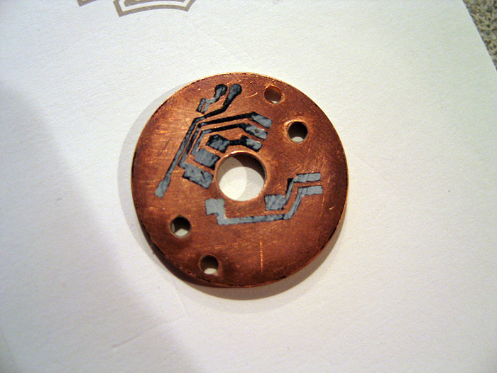
etch and you are left with your laser printer traces (covering the copper underneath)
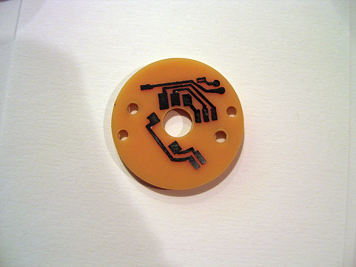
remove toner: (pcb is left)
Like Erv taught us.. pre-tin folks!
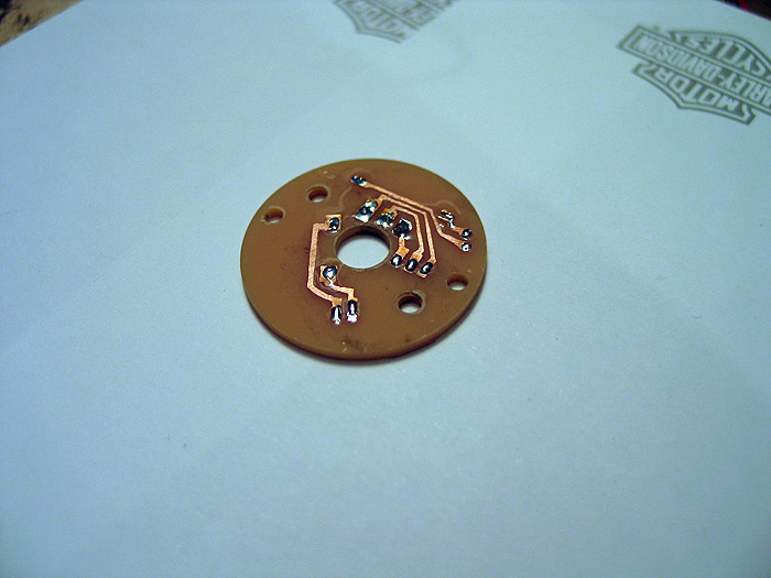
bend my switch leads underneath..and the other row down:
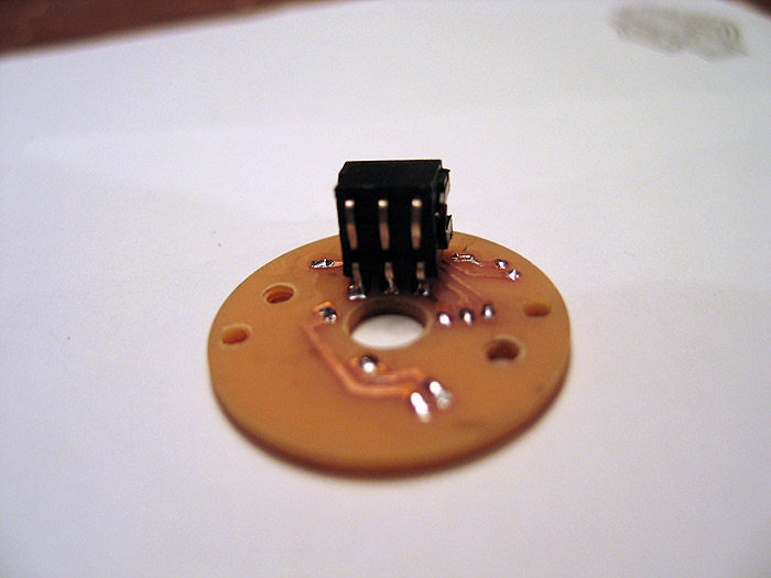
other switch:

on heatsink:
I dont have a red thumbscrew with the correct threads yet.. but you can see it mocked up there.. (screws right in from outside of hilt)
when heatsink is in MHS part.. it lines up with the holes perfectly.. (cant see it so good in pic_ =(
feedback always welcome..
hope this helps others get past road blocks in their projects!
thanks
PoC: Expanding Hilt – Part I
So I have been working on & off on an expanding saber..similar to the those hilts that have the exposable crystal chambers/core...etc
except this idea is NOT to reveal anything.. it is a step to make a more 'functional' (moving) type saber.. allowing for maybe smaller footprint (and concealment) into an expandable, longer hilt when needed/being used.
this is NOT finished.. and for those of you who have a problem with projects being posted while NOT completed.. simply fuck off. ![]()
Its in the R&D forum.. and I see people who do placeholder posts all the time.. so if you havent done anything like the above...then speak out.
anyways.. while developing/working on this.. I discovered several paths this could take.. and I also would like to get soem feedback on areas I am un-clear on how to proceed.
This is a long post.. outlining several of the ideas or variations that could be done.. and Im a long winded guy.. again.. if this a problem for you..
ALT + [F4] is a good choice for you right now.
Project goals/tasks or ideas that needed to be accepted or thrown out. (no order)..and to keep ideas out, posted for me to reflect on.
1.) smallest footprint when 'closed'..... (good idea.. nice small footprint).. but when open..what are you 'left' with as a saber?
grips both top and bottom? the extension piece?
2.) when open? form vs function... the function is there.. no doubt.. but when trying to keep/adhere to certain restrictions (like #1 above)..as well as make it visually pleasing.. it somewhat limits normal thinking/ideas.
3.) when closed..how to lock?
* I have a few locking ideas..each fairly unique..
* a outward 'clasp' (so to speak) that locks the top portion down/closed
* a 'threaded' end that is similar to sloth's reveal hilt.. the top section slides down..and can be turned/screwed into the bottom section.. (unscrew it expands..etc)
* a ballbearing/spring type lock.. Madcow used one on his hilts...as well as in use all over the world
4.) when open..how to keep from spinning/rotating.
* as of now..this doesnt need to be implemented.. BUT.. I have thought it out.. (will post pics/drawings really).. and is similiar to the sliding 'rail' chassis system I had been messing with a while back..and should work easy enough..
5.) movement/functionality
* how much movement is enough? or not enough?
there is a 3 way approach to the movement..
you slide the TOP section
you slide both 'core' * top sections
you secure top half..and make the 'code' slide (making the top section move as well of course)
so there is room for several variants..with different movement here as well..
to explain the parts/mechanics:
required:
2 x double male threaded connector (old style ones need to be modified... new version will need a custom part sleeve/shim (Super Mario Bros. Tunnel) for them to be compatible... I have used one of each for this demo/display)
a custom OD section of tubing (your sliding 'core').. with a LIP on the end..the same OD as a heatsink
1 x 1.25 OD spring (length to fit your project travel)
the rest of the MHS parts you use is up to you..and how much TRAVEL you want..or how you 'pull it all together'.. this is just the mechanics of getting an expandable hilt going..
this is (was) a WIP.. and if you dont like.. fuck off. ![]()
re-cap:
if you dont like un-completed projects...dont have anything constructive to say.. move along. Im sure there is a conversions section somewhere.
could be a cool effect for a staff too.. double ended, expanding sides/pop-outs..
**(taking pics in a little bit)..
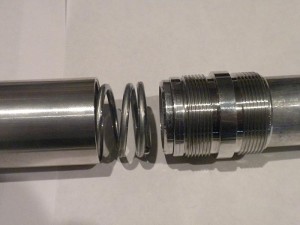
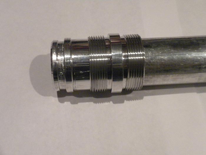
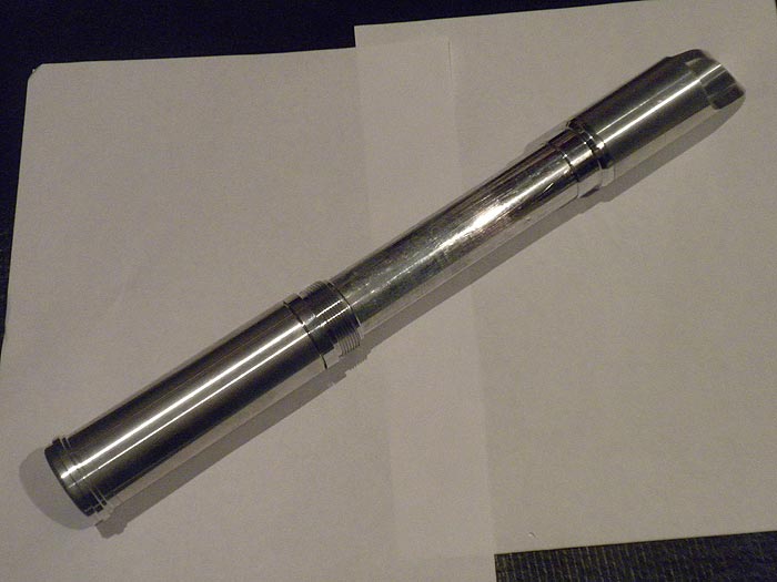
pic of the part(s) used.. you can see BOTH of the double ended male threaded connectors in use here..
the one with the threads left on was/is on purpose to try a certain 'locking approach'
if not using that route for locking..the threads would be turned down/off to mirror the other adapter/collar
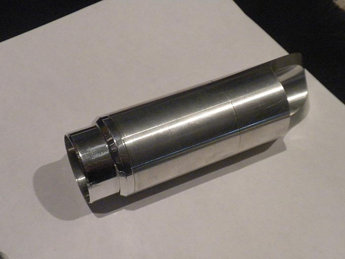
you can see the collar/sleeve fix I had to make for the the lack of OG adapter part..and to be used with the new ID ones. (looks like a Super Mario bros. tunnel)..it slides inside the adapter (new version style)
spring and 'core' as well pictured.
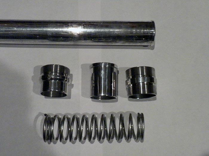
fitment is great on all parts! (happy with it)
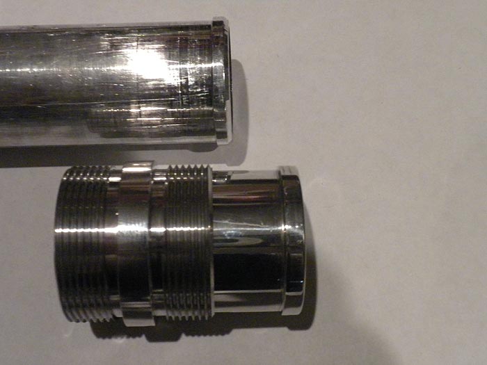
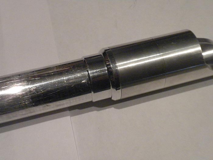
OG Double Male Threaded Adapter, that has been bored out..and the threads turned down: (reminds me of brass bastard a bit)..
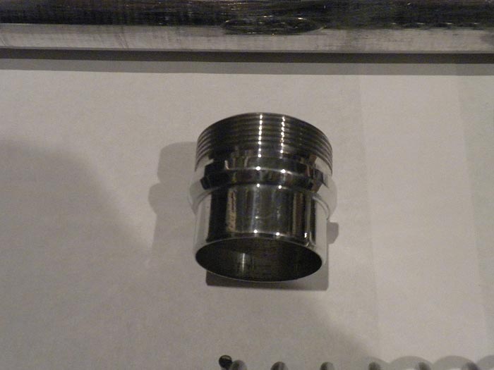
and would look great for dressing a choke to a regular MHS part normally..not in conjunction with this sliding/expanding project
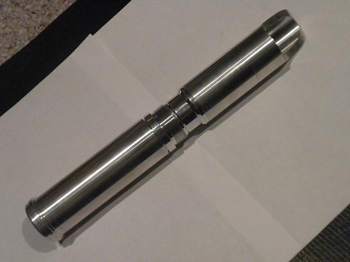
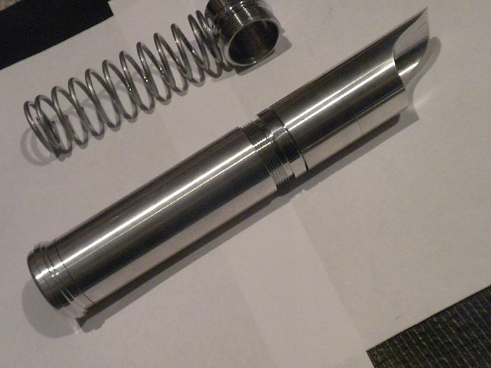
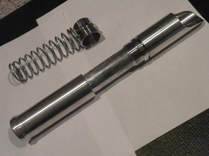
here it is one of the possible 'closed' states: (in this version since BOTH pieces have the external collars... the threads would be turned down.. to match the top collar..)
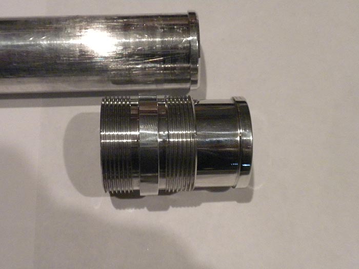
a better look at the 'core' (sliding system)
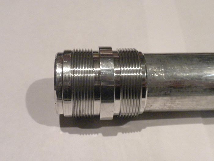

using the adapter..and leaving a lip on the core/tube..
I can screw it right into any MHS male part.. and effectively have a 'plunger' now.. the core tube will NOT come out. (not does it spin either surprisingly)
please excuse the super long-ness.. I have NOT committed to cutting the core/tube yet, until I am SURE on the levels of expansion and the locking portion of this project
rant:
(the longer the MHS part..the more travel, you can obviously get.... however that doesnt leave much for practicality in the visuals or the design.. since you dont really want a SUPER long, goose necked choke/core.. a nice 3 inches looks good visually ... but you also want the smallest footprint you can do when the saber is closed...unless its more for a quick effect or on a staff or something.... so that means shorter MHS parts.. and back to less travel then... however you can make both the top section..and the middle/core tube BOTH expand while holding the grip section) so you need to play with balance & direction a bit.
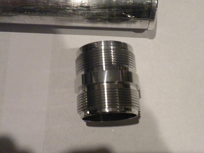
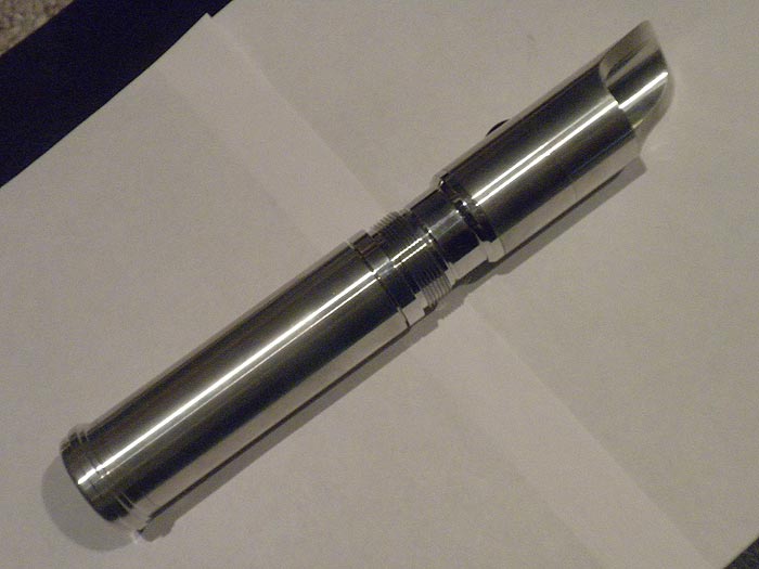
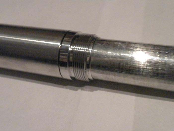
Locking approach #1:
forget the bottom 'collar'.. I have an internal 'ring' that supports the core/tube still.. but I leave the threads on the top collar..
collapse..and then spin the handle portion to lock into place?
un-screw...pop:
LOTS of paths I can take here.. with locking (hard part).. and choosing the expansion path more than one section expanding? or just one?..etc
cold here, not to mention time is absent alot these days... so like the bearing chassis pommel lock mod...figured Id just share what I have.. maybe it will help someone else.. (not to mention this one I could use some ideas on)