MHS [modified] control box (my entry in cram-fu)
been playing around with a few ideas over the years.. and have worked on a few control box ideas/projects as well...
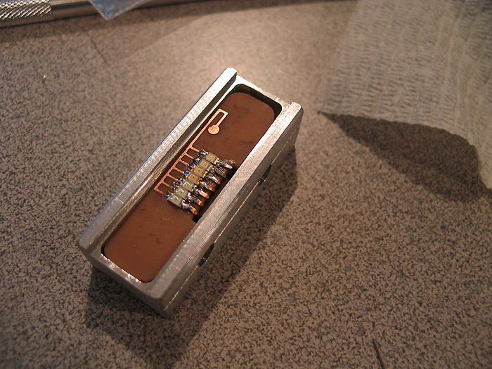
this one is based off an MHS control box.. with some 'modifications' ![]()
things to note:
*has two switches (main and aux) in it.. (one the 'side' of the box.. with custom switches and switch caps/stems
*custom PCB was created for them to mounted, to and mounted to the inside of the box.
*has a 1.3mm recharge port in it
* has custom smd led bar graph (custom made pcb for this as well)
pretty has everything a hilt needs, all located in the......... 'control box' ![]()
posting my mock up pics... if things work out good.. (which it look sot be great even).. I'll break it down again.. re-fine...and buff/polish and powder coat for the finished product.
hopefully this gives some ideas for everyone else... make things work for you!.. make what you need...
lets begin:
1.) take your favorite drawing app and make a PCB design.. no special tools.. draw BLACK lines/traces and pads where you want 'copper' to be..
get your copper clad board/section..
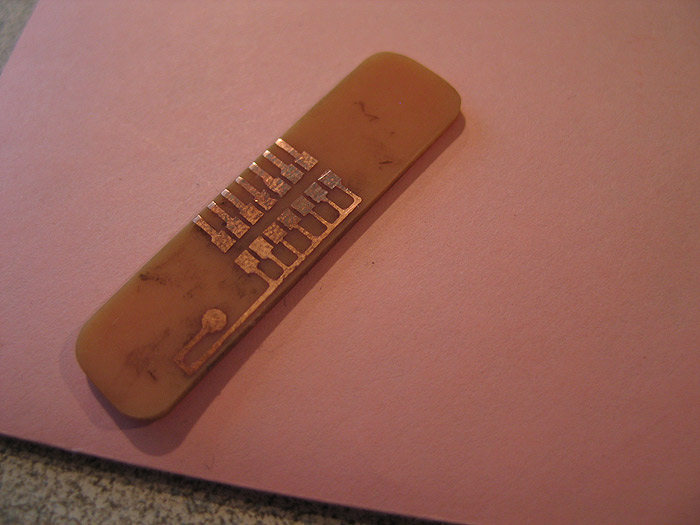
2.) print out image on glossy photo paper.... iron/transfer image/toner to the copper board.. rinse under water to remove paper.. soak in etchant to remove exposed copper:
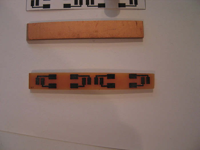
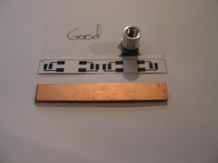
3.) after exposed copper is gone.... use a q-tip and some mail polish remover to remove the toner from the pcb... (revealing the copper/pcb under neath)
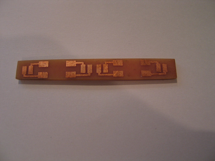
***(all this above has been posted many times before.. and shame on you for not trying it!... this could have saved your ass in that 'one' project!) =)
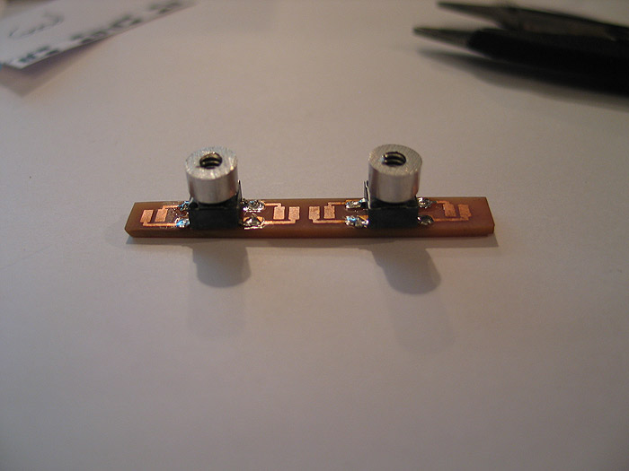
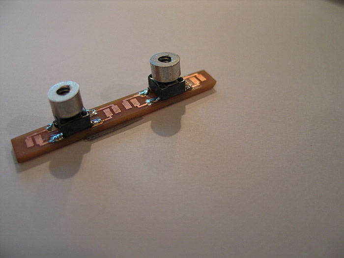
4.) mounted my modified switches to their PCB.. (these have the threaded tops on them for external switch caps to be used form outside the hilt.. keeping the main core/chassis/box internals standalone)
several solder pads depending on the need/space available
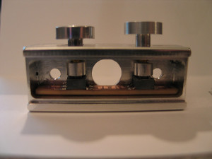
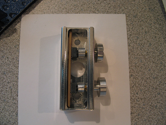
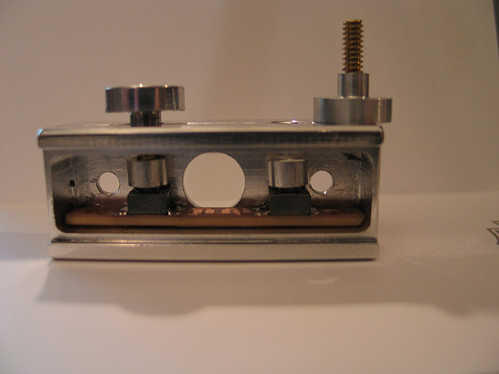
5.) mounted (mocked up) in the control box:
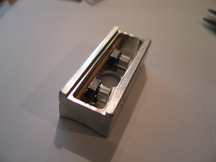
6.) (although it looks 'off' its really just the pic.. things line up great!)
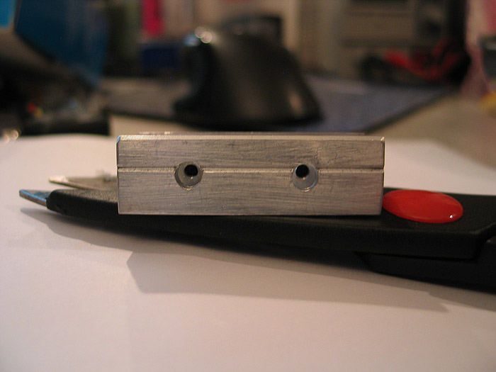
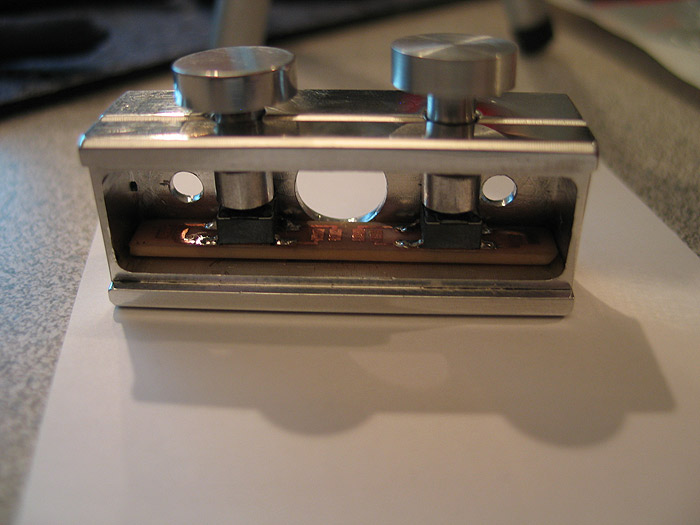
side view of holes and where the switch tops are
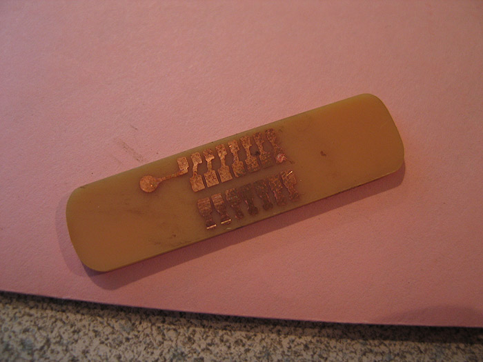
7.) top (custom) pcb made..for the led bar graph.. (this posed a problem due to space.. and the fact that I wanted each led to be addressable for either all direct drive..'or' for CF led.txt sequence..etc.. not to mention trying to do double sided board without through hole plating.. (making my own)..
again.. space was concern.. (both sides)
I think an led (possible two) got ruined by heat? or something.. but Im going to replace them real quick. (as they only light up partially)
in the end it will be black box.. aluminum top plate and aluminum switches on the side of the box.
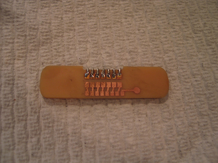
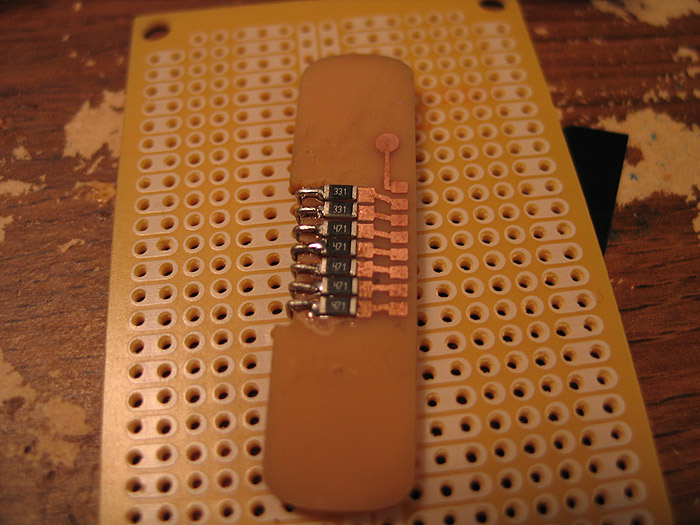
the top 'smd led bra graph' pcb/portion
this is where each resistors goes: (bottom of board)
quick mock up:
(again the switch pcb is in place already.. the custom pcb's are almost forming a box to support each other
---------------------------------------------------------------------------------------------------
got a couple hours the other night to finish 95% of it up... (I think 'real' professional PCB's would serve best here)
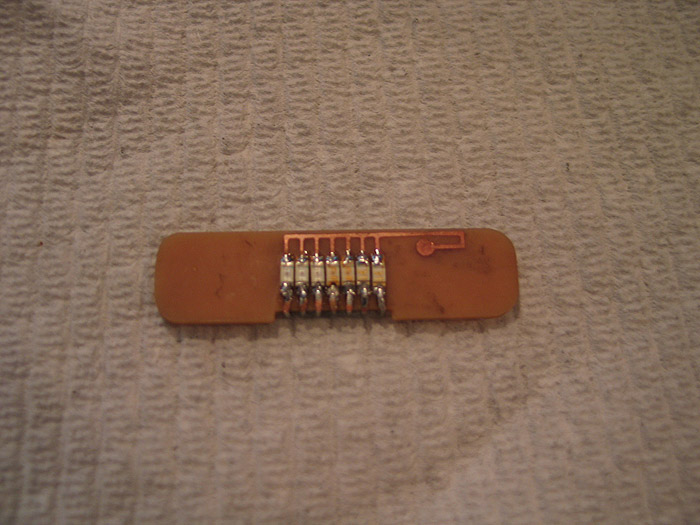
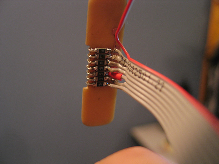
got the bottom half of the bar graph competed (resistors soldered, wires soldered..etc)
used 1206 resistors.. all I had at the time.. (yesterday my 0603's came.. had I had those in my plannign stage..I think everything might have been topside mounted....oh well v2 I guess..lol..this is my PoC)
still not quite sure how/where to tap the V++ to.. I have a few ideas...not a big deal though any place will work) ![]()
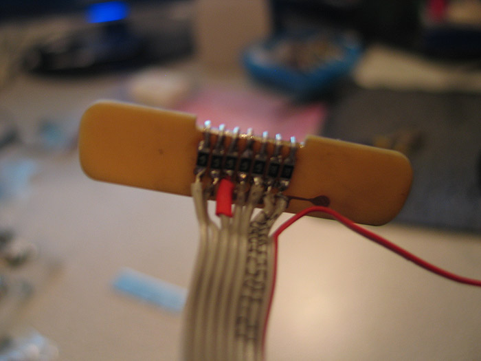
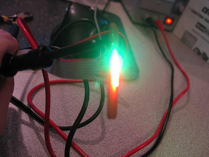
quick test of being lit up.. (had to replace 2 leds as I think they were 'damaged' by initial placement? maybe soldering too hot? different bin? one was of color.. when lit up bright..then gradually died out after a few seconds)..anyways replaced them
2 x green
2 x yellow
3 x red
each resistored, each individually addressable... (so can be direct driven, used with CF, or as PLI) =)
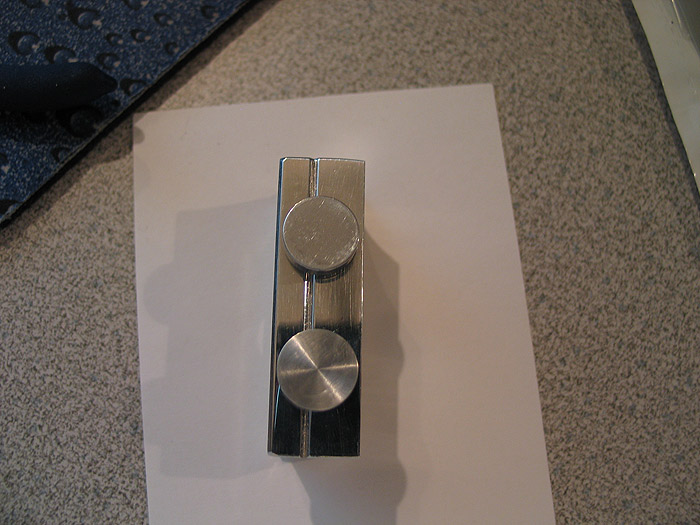
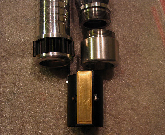
quick mock up of the side/switch PCB inside the box. and the switches/caps/stems I made for them.. (still need to be shortened a bit..but they are close enough to work and show the effect/style)
more pics of the 'switch caps/stems'

the pcb's took about 30 minutes total to make.. (probably another 15 prior on trial and error on printing out paper copies and doing size checks)
now that I feel the idea is 'sound' I'll go back and plan it out a bit better.. (this is supposed to still have recharge port added..but Im not sure after implementing things this far it will make the cut)
time to break it down.. pc the control box BLACK..
buff/polish the 'switches'...
and complete the 'top'.. which is an already sized aluminum strip that sits flush like any normal 'card stock'
there is NOW window cut/milled out of it yet through for the bar graph.. =(
enjoy.
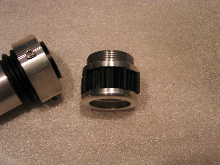
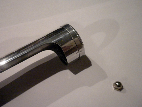
AoF Pommel (mod)

AoF Pommel (mod)
Got some pommels made from Randy a few (years?) back now...
they were oversized (OD).. because most MHS pommels were stock OD..
it is very similar to the Jay-Gon pommel #10 that is in production now..
I like them because:
a.) using a shroud/sleeve/overlay isnt BIGGER than the pommel OD now..
b.) it helps 'lock' in overlays because they cant slip past/over the pommel..
You can see an original one on the right...and the mod'd one on the left.
(some turning down..and trimmed up t-track)
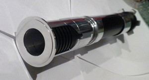
on a hilt/extension section:
Close ups:
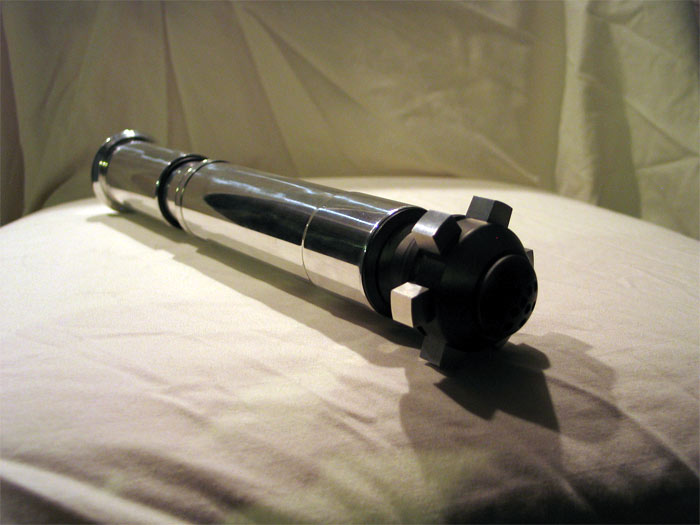
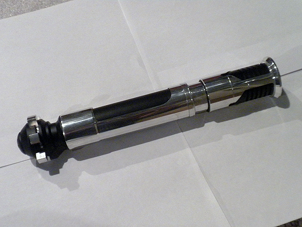
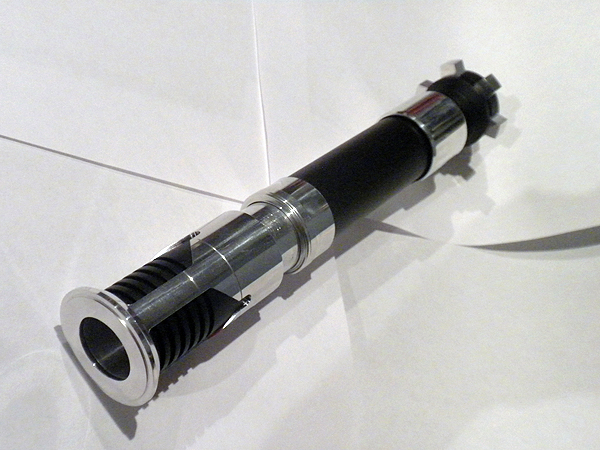
Custom/MHS OBI-TPM (hybrid)
ok..so this has been on the burner.. for....well for a long time actually.. I sorted started it when I saw Obi-Dar posted his build start...
it was shelved.. as I didnt care for the route I was taking at that moment....
anyways did some more work on it.. and here is where I am at.. figured Id get some feedback..
I think it looks a bit 'weird' to me because there are no cut-outs in the shroud/emitter yet..(Im hoping thats all it is!..lol)
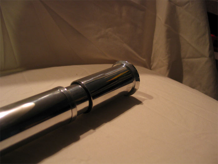
as far as being an 'exact dup' in dimensions.. its of course not.. (its no ACE OBI TPM to be sure, spot on with awesome machining) ![]() .. 'but'..its not that far off from the dimensions I got on-line.... the most notable place is the main hilt 'OD'.. which will mostly be cut away so I dont think it will have that much effect on the final look... every thing else is exact or a not 'too bad'...
.. 'but'..its not that far off from the dimensions I got on-line.... the most notable place is the main hilt 'OD'.. which will mostly be cut away so I dont think it will have that much effect on the final look... every thing else is exact or a not 'too bad'...
overall length is over 11".. but little under 11.5 if I recall..
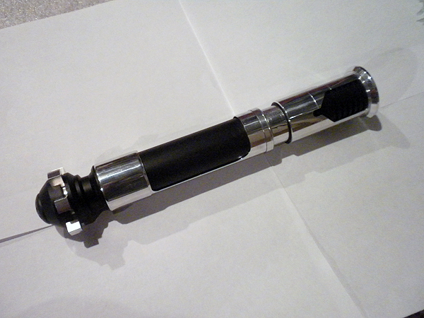
feedback is appreciated of course. ![]() things/areas to work on.. (although its not complete of course).. or things that should be re-done perhaps?
things/areas to work on.. (although its not complete of course).. or things that should be re-done perhaps?
Thanks.
(Im no photographer!)
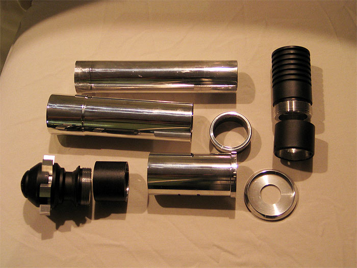
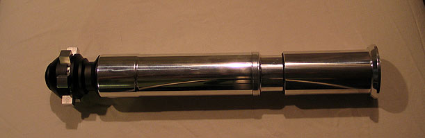
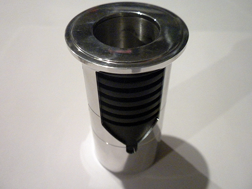
The parts used:
1 x Ace Obi TPM pommel
2 x 1.5 sink tube adapters (turned down to be 1.39 OD and faced to be roughly over 1")
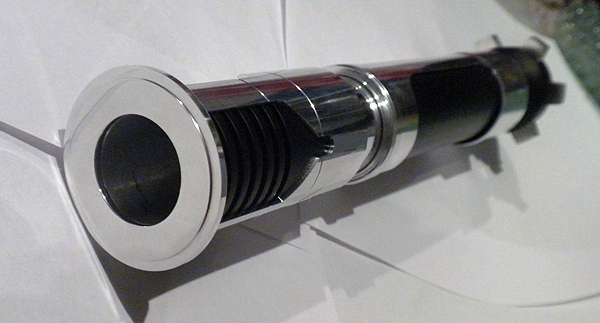
1 x 1.25 'core' aluminum tube so it has a 1.25 choke section ![]() (slightly modified to meet ID of one of the adapters I used)
(slightly modified to meet ID of one of the adapters I used)
1 x MHS BH #3 turned down to be 1.39 OD)
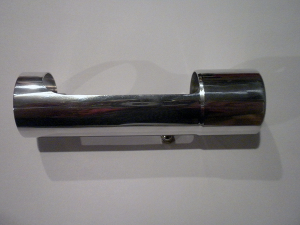
1 x custom hilt shroud ID bored to 1.39...OD to match the TPM as best I could..
1 x custom shroud ring/support for the top end which has a bit larger OD and design
1 x custom emitter shroud ID bored to 1.39 (OD has a bit of a lip/larger OD than the rest for the 'top ring")
1 x custom 'ring' taking a cue from Randy/Obi-Dar's build of course.. (and because I fubar'd my 1 piece attempt the first go-around) (DOH!) :dft001:
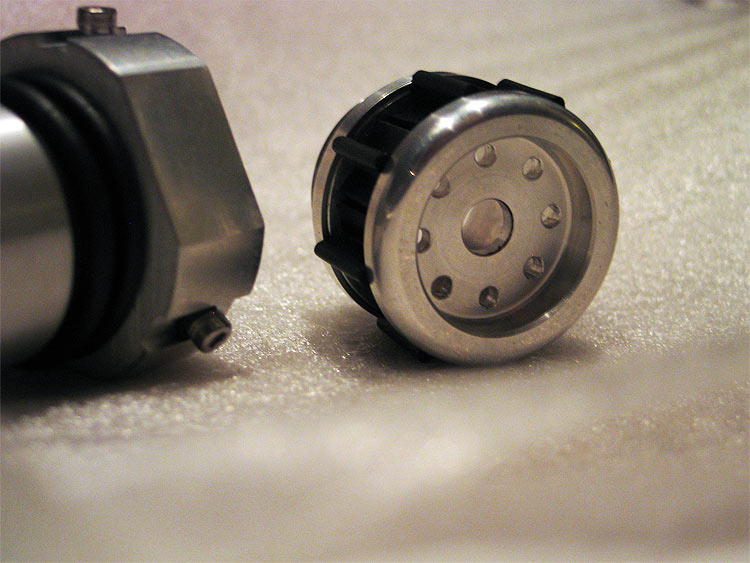
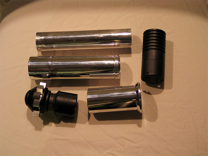
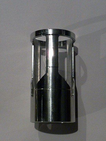
All parts
Rings attached:
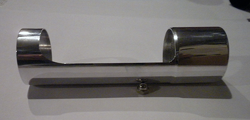
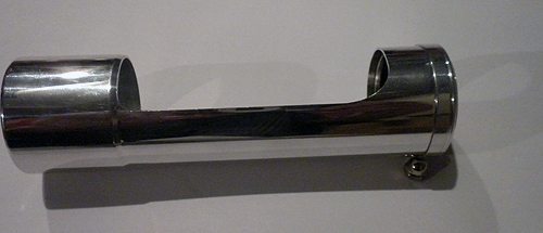
Top section:
Side:
Angle:
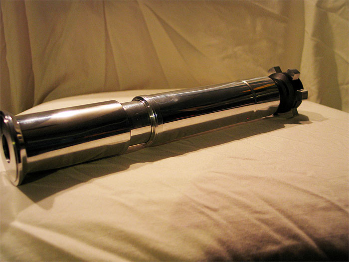
Full:
Last:
The OD of the ring needs to be opened up to 1" to accept a blade still.. but thats really only about 10 minutes of work to do..
if it passes the test(s).. then I'll work on the shrouds or something.. wire it up.. and see what board it gets (if any)..
if it goes over well.. I always have the 'rule of two' for builds.. and there is parts to make another ![]()
Thanks gang.
-------------------------[update II]------------------------------------
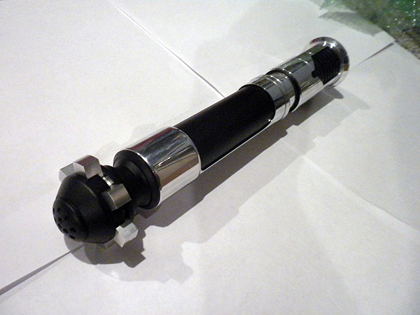
just some quick update shots:
got the 3 windows in the top emitter shroud and the window in the grip shroud cut out by Tim (great work too, thanks Tim)
bike value
some bezels
and the delrin 'grip section' and I can focus on internals..
not sure if it will be than board/battery pack etc...
not too much room for a chassis!
some pics.
(I think she is turning out very nice.. no "Erik/Ace" version!..lol.. but nice to me!) and not too fat/chubby.
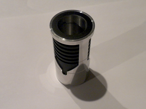
the shroud and BH fit like a glove.... and Tim's window cutout make it look so nice.
I put the lines/grooves in just about the perfect spot with the BH and the modified adapter 'seam' makes it less noticeable
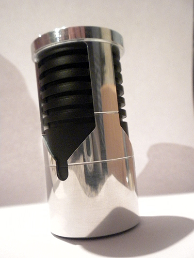
Heres a pic with the ring on and all together.. (pic isnt so great..its look nice in person.)
more pics of the sleeve I turned down..with slight dip/bevel that i sent to Tim to be cut out.
A pic with the sleeve and the 'collar/ring' for the 1.25 inner and sleeve connector/support. (this part is being re-done for better tolerance fit....that god its not a hard part at all!..)
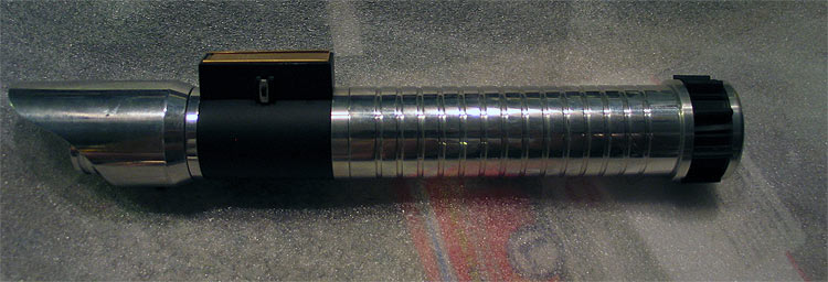
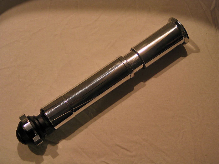
Some side/full length views:
no delrin inner grip section.. just a 'temp' all black filler...lol
hopefully I'll get some free time to wrap up the hilt stuff.
Thanks