Another SMT stencil cutting post….
Finally some results! ![]()
I recently purchased a Silhouette Cameo (http://www.silhouetteamerica.com/?page=shop&cat=1)
Aside from all the things that can be done with this machine (cut fabric, vinyl, paper/card stock, etching plastic, cut cake fondant, stickers, signs, wedding cards/invitation, and the list goes on and on...) one of the things I wanted most was to be able to cut SMD/SMT stencils for making pcb's at home.
It has been a 'trend' lately, seeing the idea pop-up on HackADay , IdleLoop, DangerousPrototypes, and other blogs/forums.. so I decided to get to work on what it woudl take for me to produce the same results.
First I want to give a shout out and credit to several people/places as nothign I have done here is 'new' or innovative, its just the results from the hard work and sotware of other people, who decided to share with us, for this purpose. ![]()
HackAday, Idle Loop, DangerousPrototypes, Pmonta, teletypeguy, jessuscf...and everyone else I forgot.. ![]()
http://hackaday.com/2012/12/27/diy-smd-stencils-made-with-a-craft-cutter/
http://www.idleloop.com/robotics/cutter/
http://pmonta.com/blog/2012/12/25/smt-stencil-cutting/
http://dangerousprototypes.com/2013/05/17/cutting-stencil-using-a-silhouette-cameo/
(Im sure there are others.. but these were mains one..and they all link to each other or have a list of links in the articles themselves to oter relevant info)
With that out of the way..
the general overview of everything I have tested and read basically boils down to, there are only to 'viable' approaches that are worth the 'effort'.
Approach 1: Involves exporting a .dxf file directly from SoftCAD Eagle pcb design software, and you inturn import that .dxf file into the default Silhouette Studio software that comes with you Silhouette Cameo.
This is the approach outlined here at:
IDLE LOOP - http://www.idleloop.com/robotics/cutter/
by Cathy Saxton
The ULP script is located here on github: https://github.com/SWITCHSCIENCE/ssci-eagle-public/blob/master/cream-dxf.ulp
(not sure of the author..sorry)
* Dont forget to turn off "scale to fit" for DXF import in your Silhouette Studio preferences.
This is by far the EASIEST approach one can do/try... (its not much different than using your Cameo to open/cut any other .dxf file at this point.
However.. the results were 'ok' (at best!).. and with soem tweaks 'usable' probably with some 'fixing' afterwards..
I experienced the same results as many others on the net have experienced..
not 'straight' cuts.. bowed out box lines, alignment problems..etc
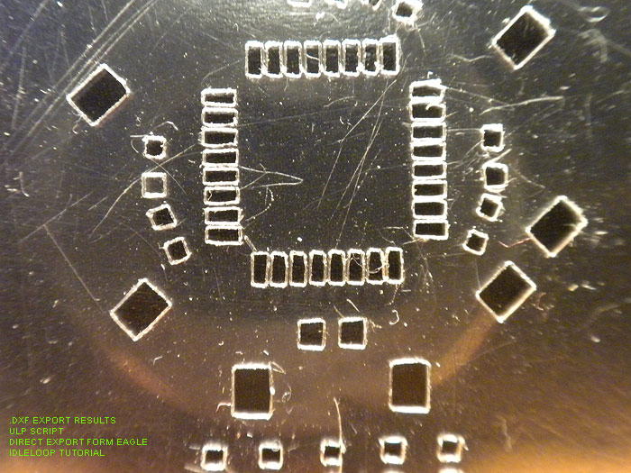
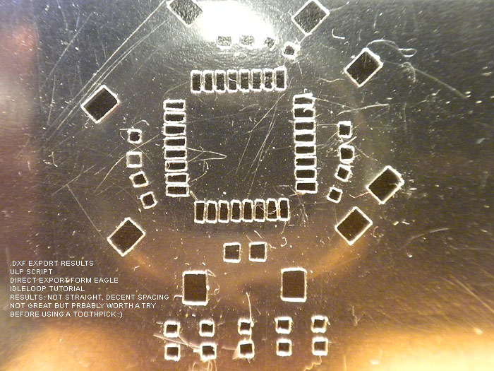
Results: 'ok'.. probably 'usable', maybe with some fixin'/clean-up..
better than a toothpick and doing it by by hand I would imagine. ![]()
Next up is the GerberToGraphtec approach. This works DIRECTLY with the gerber file exported from your design software..
and is Python based...
This script/project is by: Peter Monta
http://pmonta.com/blog/2012/12/25/smt-stencil-cutting/
Github files: http://github.com/pmonta/gerber2graphtec
Being on Windows. this was a bit of a learning curve, and require the installation of several supporting apps.
(and not to mention I'm pretty much command line retarded)
Anyways.. download and install these app sin their default locations:
Python 2.7.5: http://www.python.org/
Gerbv 2.6.0: http://sourceforge.net/projects/gerbv/files/gerbv/gerbv-2.6.0/
pstoedit 3.61: http://www.pstoedit.net/
Ghostscript 9.07: http://www.ghostscript.com/download/gsdnld.html
As mentioned here: http://dangerousprototypes.com/forum/viewtopic.php?f=68&t=5341#p51495 in a post by: jesuscf..
he mentioned, for WINDOWS USERS.. we need to edit the gerbertographtec file.. (from what I have read it 'just works' for Linux and Mac.....figured I'd mention it to make you guys happy)
Download the .zip file and extract the folder inside...
Find the gerbertographtec file and edit it as follows:
1.) add the .py extension to the file name (to be able to run the program directly from a command prompt)
2.) Change these two lines:
os.system("gerbv --export=pdf --output=%s --border=0 %s" % (temp_pdf,input_filename))
os.system("pstoedit -f pic %s %s 2>/dev/null" % (temp_pdf,temp_pic))
to:
os.system("\"C:/Program Files (x86)/gerbv-2.6.0/bin/gerbv\" --export=pdf --output=%s --border=0 %s" % (temp_pdf,input_filename))
os.system("\"C:/Program Files/pstoedit/pstoedit\" -q -f pic %s %s" % (temp_pdf,temp_pic))
*He mentions this is because some of the apps above (gerbv & pstoedit) added their executable folders to the path.
One of the final steps is 'sharing' out your Silhouette Cameo printer, in the Printers & Faxes screen in the Control Panel.
(right click >> sharing & security >> share this printer (name it: Cameo)
At this point, I had some problems with the command line stuff he was posting to use to initiate the process and start cutting:
C:\gerber2graphtec-master>gerber2graphtec.py test.gbr > result.txt
C:\gerber2graphtec-master>copy /B result.txt \\[YOUR COMPUTER NAME]\Cameo
alternate line to use: (not tested)
C:\gerber2graphtec-master>gerber2graphtec.py test.gbr > \\[YOUR COMPUTER NAME]\Cameo
I had tested things as described and kept getting error after error.. (not sure if it was a pathing problem, or installation problem on certain supporting apps)
either way.. I ended up just using a .bat file another member (teletypeguy) posted, and uing the same file structure.
that ended up being this:
on _root of C: drive:
Create a folder called: gerber-files-to-cut
ie: C:\gerber-files-to-cut
INSIDE this directory, you put/copy the gerbertographtec folder you downloaded at the github link above (dont forget to edit it as outlined above)
ie: C:\gerber-files-to-cut\gerber2graphtec
and the .bat file I created/used was this: (use your computer name, not [computer_name]
@echo off
rem This is for printer named "Cameo" which must be named and shared in control panel.
rem This is for computer named "hacker"
echo.
echo This script will send gerber file to Cameo for cutting solder stencil.
echo Generates intermediate files .pdf, .pic, and .graphtec.txt
echo.
echo Set your Cameo blade to 1 and turn cutter on.
echo Load mylar sheet (landscape) at upper-left corner of mat.
echo.
set /p filename= Enter filename of gerber (eg: test.spt or board.gbr):
gerber2graphtec\gerber2graphtec.py %filename% > %filename%.graphtec.txt
copy /B %filename%.graphtec.txt \\[computer_name]\Cameo
This .bat file should be INSIDE of the: ie: C:\gerber-files-to-cut directory.
At this point.. you are ready to startm aking test cuts.
Be warned, this a VERY SLOW process, but very accurate and te results are pretty good.
2-passes, pretty much 'stock' configuration
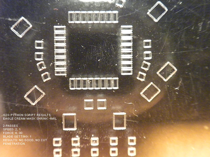
did NOT cut all the way through!!!.. but looked good (pic doesnt really do it justice as the shadow and it didnt cut all the way through making it look 'fuzzy/choppy'.
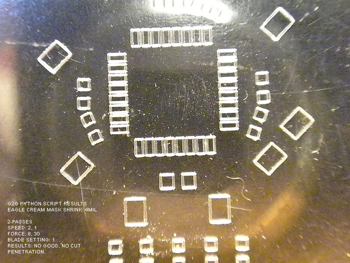
Edited to 3-passes
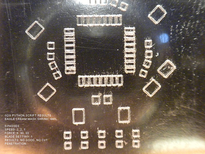
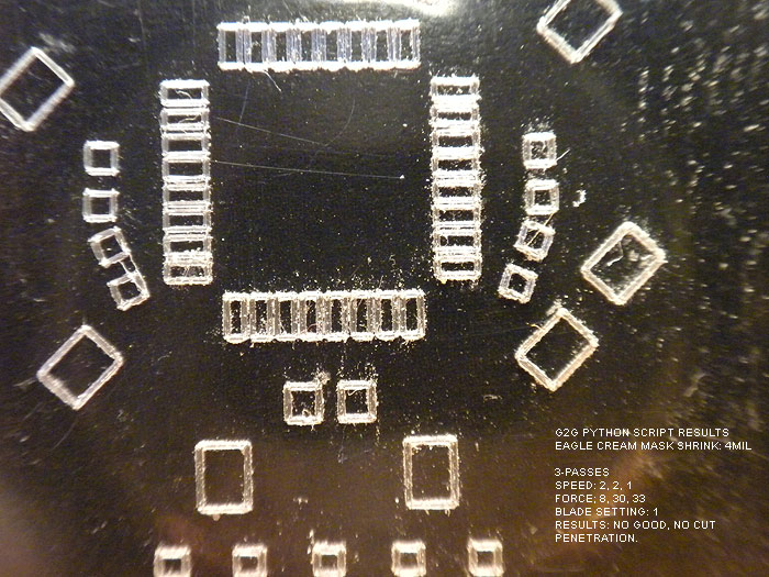
result: still couldnt get the cut to penetrate..(backside was still smooth)
ok.. so at this point.. Im thinking: "Geez, the ULP script and .dxf export from IDLE LOOP looks great right about now!" LOL..
no matter what a BLADE SETTING of 1 wont cut it!.. and the holes never were cut out.
blade setting of two was too much and ripped pads!
but I kept reading around and asking questions, and was informed about the defaults in the gerbertographtec.py script..
(about how to add more than 1, 2, 3 cuts, and the force (pressure) parameter as well!)
This,.. in addition to the tip on shrinking the CREAM layer in the DRC >> MASKS tab, seemed to charge new life into me!
So I opened the gerbertographtec.py script (I also learned you can add these parameter to the batch script, but I think I was more comfortable editing the .py script itself, and commenting out other 'settings' for later review/use
found these lines/values:
offset = (4,0.5)
border = (1,1)
matrix = (1,0,0,1)
speed = [2,2]
force = [8,30]
cut_mode = 0
and edited them...
the only one I really messed with was speed & force (although by default the script will cut a 1" board around your pcb largest area.. you can change this in the border default)
(all images should have the settings used and the results in the image)
Also note that I tried to shrink the CREAM LAYER in Eagle before exporting by 6mil.. and it looked/showed no different than when it was at 4mil.... not sure if it is due to the iTeadStudio CAM file I used to export the gerber files or what?
either way Im happy and impressed with the result so far:
keeping the blade setting at 2..I tried different runs, speeds, and pressure..
here are the results:
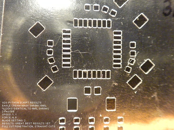
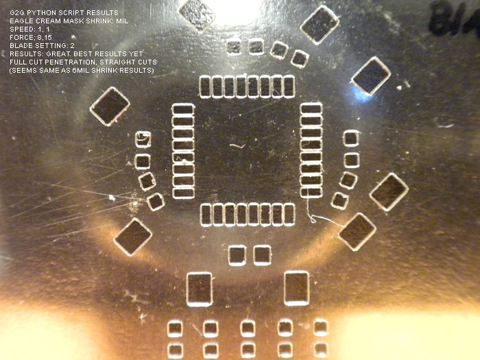
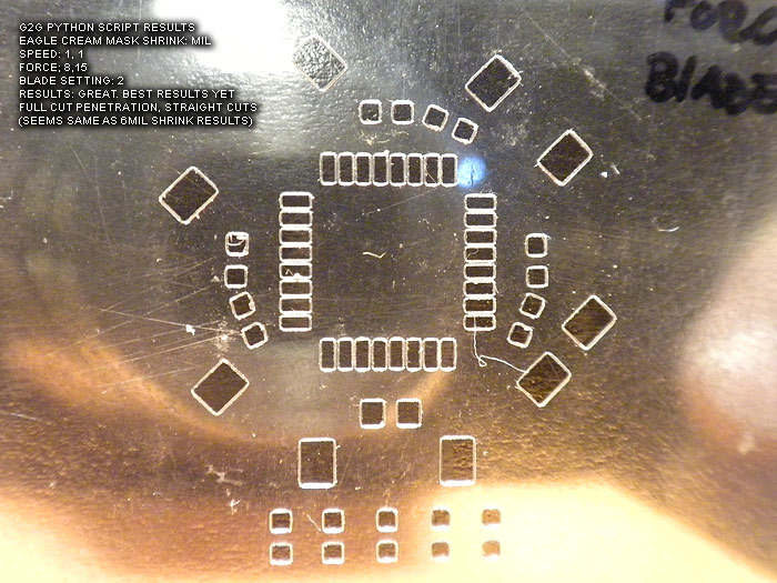
At this point. I believe these to not only be usable.. but of 'decent' quality.. (better than the laser ones I have 'paid for perhaps?)...
I am going to be trying the Apollo write-on transparency sheets from the local Home Depot this weekend.
*Project note:
I still get an error/warning every time I run this...
"The procedure entry point ?construct@?$allocator@VVPath@Magik@@@std@@QAEXPAVVPath@Magik@@$$QAV34@@Z could not be located in the dynamic CORE_RL_Magik++.dll"
*****update: by removing the .dll from the directory, this solves the error..
it has to due with either gerbv or pstoedit (I cant re-call off hand).. however I have even tried installing Image_Magik..to get the .dll's and copy/paste them to the directory.. (error persisted)
Love to hear what anyone has on this error and how to fix it!
thanks to all the hardwork and posts of everyone before me and where I source the info/help from!..
its a great 'tool' to have, and a nice ability to not have to source/pay for solder paste stencils any more for hobby/protype work!
update:
at the Dangerous Prototypes forums.. there have been additions done by the members..
* a new .py script hat is optimized for not only faster speed.. but seems to perform better/straighter cuts through the entire stencil/area
* a new GUI for editing the parameters and fine tunign control as been created as well
* Linux and MAC support for the GUI...
IMHO.. this was worth the purchase of my Silhouette Cameo alone.. ![]()
thanks!