Another SMT stencil cutting post….
Finally some results! ![]()
I recently purchased a Silhouette Cameo (http://www.silhouetteamerica.com/?page=shop&cat=1)
Aside from all the things that can be done with this machine (cut fabric, vinyl, paper/card stock, etching plastic, cut cake fondant, stickers, signs, wedding cards/invitation, and the list goes on and on...) one of the things I wanted most was to be able to cut SMD/SMT stencils for making pcb's at home.
It has been a 'trend' lately, seeing the idea pop-up on HackADay , IdleLoop, DangerousPrototypes, and other blogs/forums.. so I decided to get to work on what it woudl take for me to produce the same results.
First I want to give a shout out and credit to several people/places as nothign I have done here is 'new' or innovative, its just the results from the hard work and sotware of other people, who decided to share with us, for this purpose. ![]()
HackAday, Idle Loop, DangerousPrototypes, Pmonta, teletypeguy, jessuscf...and everyone else I forgot.. ![]()
http://hackaday.com/2012/12/27/diy-smd-stencils-made-with-a-craft-cutter/
http://www.idleloop.com/robotics/cutter/
http://pmonta.com/blog/2012/12/25/smt-stencil-cutting/
http://dangerousprototypes.com/2013/05/17/cutting-stencil-using-a-silhouette-cameo/
(Im sure there are others.. but these were mains one..and they all link to each other or have a list of links in the articles themselves to oter relevant info)
With that out of the way..
the general overview of everything I have tested and read basically boils down to, there are only to 'viable' approaches that are worth the 'effort'.
Approach 1: Involves exporting a .dxf file directly from SoftCAD Eagle pcb design software, and you inturn import that .dxf file into the default Silhouette Studio software that comes with you Silhouette Cameo.
This is the approach outlined here at:
IDLE LOOP - http://www.idleloop.com/robotics/cutter/
by Cathy Saxton
The ULP script is located here on github: https://github.com/SWITCHSCIENCE/ssci-eagle-public/blob/master/cream-dxf.ulp
(not sure of the author..sorry)
* Dont forget to turn off "scale to fit" for DXF import in your Silhouette Studio preferences.
This is by far the EASIEST approach one can do/try... (its not much different than using your Cameo to open/cut any other .dxf file at this point.
However.. the results were 'ok' (at best!).. and with soem tweaks 'usable' probably with some 'fixing' afterwards..
I experienced the same results as many others on the net have experienced..
not 'straight' cuts.. bowed out box lines, alignment problems..etc
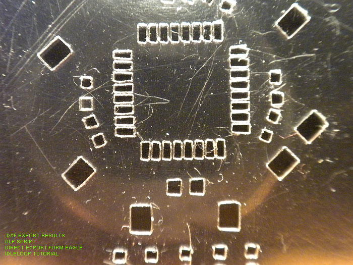
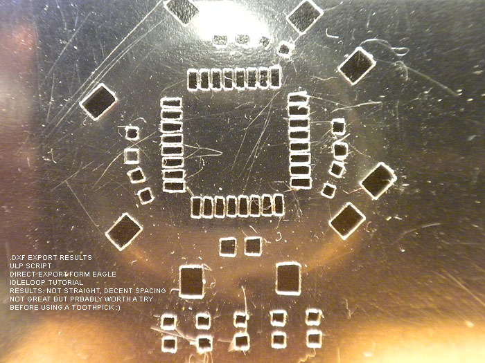
Results: 'ok'.. probably 'usable', maybe with some fixin'/clean-up..
better than a toothpick and doing it by by hand I would imagine. ![]()
Next up is the GerberToGraphtec approach. This works DIRECTLY with the gerber file exported from your design software..
and is Python based...
This script/project is by: Peter Monta
http://pmonta.com/blog/2012/12/25/smt-stencil-cutting/
Github files: http://github.com/pmonta/gerber2graphtec
Being on Windows. this was a bit of a learning curve, and require the installation of several supporting apps.
(and not to mention I'm pretty much command line retarded)
Anyways.. download and install these app sin their default locations:
Python 2.7.5: http://www.python.org/
Gerbv 2.6.0: http://sourceforge.net/projects/gerbv/files/gerbv/gerbv-2.6.0/
pstoedit 3.61: http://www.pstoedit.net/
Ghostscript 9.07: http://www.ghostscript.com/download/gsdnld.html
As mentioned here: http://dangerousprototypes.com/forum/viewtopic.php?f=68&t=5341#p51495 in a post by: jesuscf..
he mentioned, for WINDOWS USERS.. we need to edit the gerbertographtec file.. (from what I have read it 'just works' for Linux and Mac.....figured I'd mention it to make you guys happy)
Download the .zip file and extract the folder inside...
Find the gerbertographtec file and edit it as follows:
1.) add the .py extension to the file name (to be able to run the program directly from a command prompt)
2.) Change these two lines:
os.system("gerbv --export=pdf --output=%s --border=0 %s" % (temp_pdf,input_filename))
os.system("pstoedit -f pic %s %s 2>/dev/null" % (temp_pdf,temp_pic))
to:
os.system("\"C:/Program Files (x86)/gerbv-2.6.0/bin/gerbv\" --export=pdf --output=%s --border=0 %s" % (temp_pdf,input_filename))
os.system("\"C:/Program Files/pstoedit/pstoedit\" -q -f pic %s %s" % (temp_pdf,temp_pic))
*He mentions this is because some of the apps above (gerbv & pstoedit) added their executable folders to the path.
One of the final steps is 'sharing' out your Silhouette Cameo printer, in the Printers & Faxes screen in the Control Panel.
(right click >> sharing & security >> share this printer (name it: Cameo)
At this point, I had some problems with the command line stuff he was posting to use to initiate the process and start cutting:
C:\gerber2graphtec-master>gerber2graphtec.py test.gbr > result.txt
C:\gerber2graphtec-master>copy /B result.txt \\[YOUR COMPUTER NAME]\Cameo
alternate line to use: (not tested)
C:\gerber2graphtec-master>gerber2graphtec.py test.gbr > \\[YOUR COMPUTER NAME]\Cameo
I had tested things as described and kept getting error after error.. (not sure if it was a pathing problem, or installation problem on certain supporting apps)
either way.. I ended up just using a .bat file another member (teletypeguy) posted, and uing the same file structure.
that ended up being this:
on _root of C: drive:
Create a folder called: gerber-files-to-cut
ie: C:\gerber-files-to-cut
INSIDE this directory, you put/copy the gerbertographtec folder you downloaded at the github link above (dont forget to edit it as outlined above)
ie: C:\gerber-files-to-cut\gerber2graphtec
and the .bat file I created/used was this: (use your computer name, not [computer_name]
@echo off
rem This is for printer named "Cameo" which must be named and shared in control panel.
rem This is for computer named "hacker"
echo.
echo This script will send gerber file to Cameo for cutting solder stencil.
echo Generates intermediate files .pdf, .pic, and .graphtec.txt
echo.
echo Set your Cameo blade to 1 and turn cutter on.
echo Load mylar sheet (landscape) at upper-left corner of mat.
echo.
set /p filename= Enter filename of gerber (eg: test.spt or board.gbr):
gerber2graphtec\gerber2graphtec.py %filename% > %filename%.graphtec.txt
copy /B %filename%.graphtec.txt \\[computer_name]\Cameo
This .bat file should be INSIDE of the: ie: C:\gerber-files-to-cut directory.
At this point.. you are ready to startm aking test cuts.
Be warned, this a VERY SLOW process, but very accurate and te results are pretty good.
2-passes, pretty much 'stock' configuration
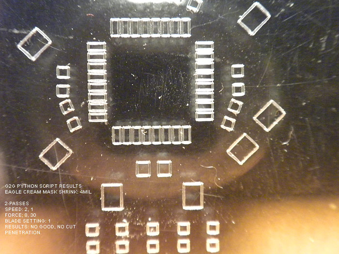
did NOT cut all the way through!!!.. but looked good (pic doesnt really do it justice as the shadow and it didnt cut all the way through making it look 'fuzzy/choppy'.
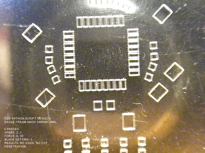
Edited to 3-passes
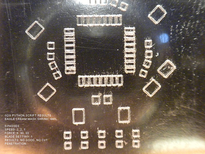
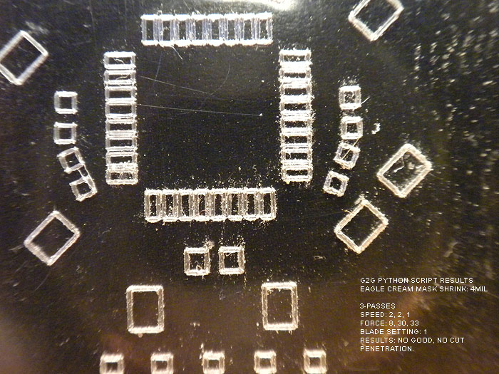
result: still couldnt get the cut to penetrate..(backside was still smooth)
ok.. so at this point.. Im thinking: "Geez, the ULP script and .dxf export from IDLE LOOP looks great right about now!" LOL..
no matter what a BLADE SETTING of 1 wont cut it!.. and the holes never were cut out.
blade setting of two was too much and ripped pads!
but I kept reading around and asking questions, and was informed about the defaults in the gerbertographtec.py script..
(about how to add more than 1, 2, 3 cuts, and the force (pressure) parameter as well!)
This,.. in addition to the tip on shrinking the CREAM layer in the DRC >> MASKS tab, seemed to charge new life into me!
So I opened the gerbertographtec.py script (I also learned you can add these parameter to the batch script, but I think I was more comfortable editing the .py script itself, and commenting out other 'settings' for later review/use
found these lines/values:
offset = (4,0.5)
border = (1,1)
matrix = (1,0,0,1)
speed = [2,2]
force = [8,30]
cut_mode = 0
and edited them...
the only one I really messed with was speed & force (although by default the script will cut a 1" board around your pcb largest area.. you can change this in the border default)
(all images should have the settings used and the results in the image)
Also note that I tried to shrink the CREAM LAYER in Eagle before exporting by 6mil.. and it looked/showed no different than when it was at 4mil.... not sure if it is due to the iTeadStudio CAM file I used to export the gerber files or what?
either way Im happy and impressed with the result so far:
keeping the blade setting at 2..I tried different runs, speeds, and pressure..
here are the results:
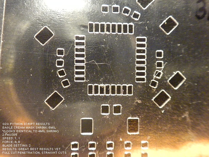
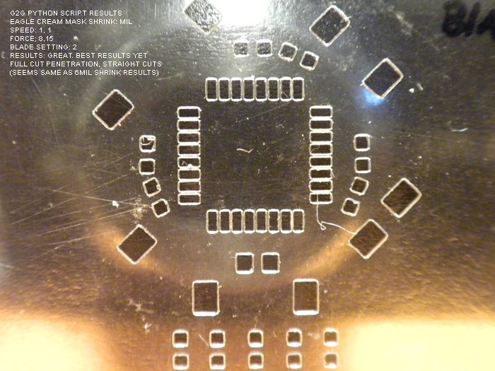
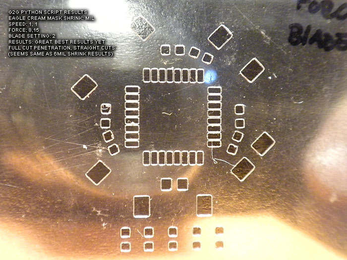
At this point. I believe these to not only be usable.. but of 'decent' quality.. (better than the laser ones I have 'paid for perhaps?)...
I am going to be trying the Apollo write-on transparency sheets from the local Home Depot this weekend.
*Project note:
I still get an error/warning every time I run this...
"The procedure entry point ?construct@?$allocator@VVPath@Magik@@@std@@QAEXPAVVPath@Magik@@$$QAV34@@Z could not be located in the dynamic CORE_RL_Magik++.dll"
*****update: by removing the .dll from the directory, this solves the error..
it has to due with either gerbv or pstoedit (I cant re-call off hand).. however I have even tried installing Image_Magik..to get the .dll's and copy/paste them to the directory.. (error persisted)
Love to hear what anyone has on this error and how to fix it!
thanks to all the hardwork and posts of everyone before me and where I source the info/help from!..
its a great 'tool' to have, and a nice ability to not have to source/pay for solder paste stencils any more for hobby/protype work!
update:
at the Dangerous Prototypes forums.. there have been additions done by the members..
* a new .py script hat is optimized for not only faster speed.. but seems to perform better/straighter cuts through the entire stencil/area
* a new GUI for editing the parameters and fine tunign control as been created as well
* Linux and MAC support for the GUI...
IMHO.. this was worth the purchase of my Silhouette Cameo alone.. ![]()
thanks!
Maverick (Nerf) Mod: custom blaster build log

Looking to do a Nerf gun mod... wanted to get some feedback on how to paint/weather it..
found a few projects on-line that I thought we pretty decent.. trying to decide on my own direction here.
1.) black & silver based (techy) theme
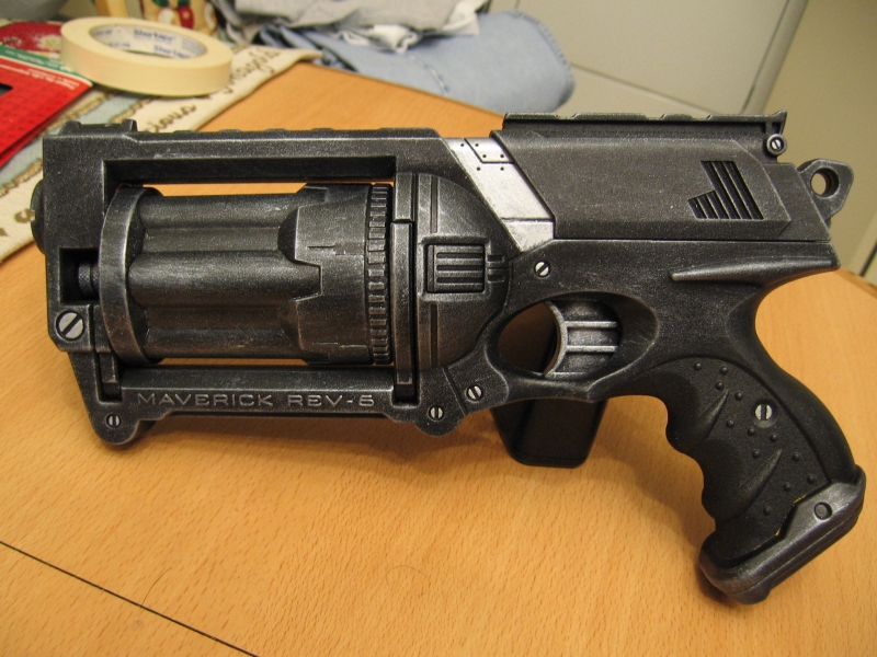
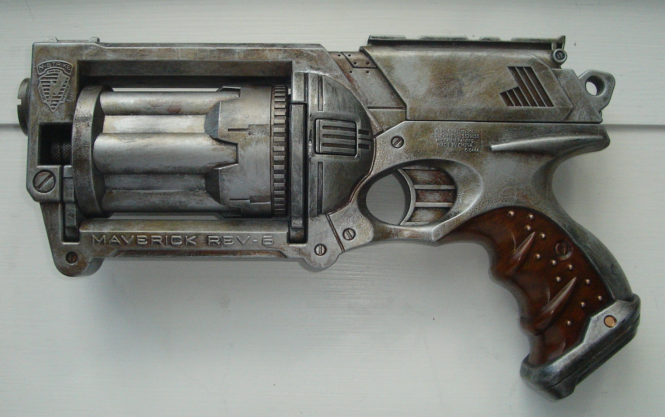
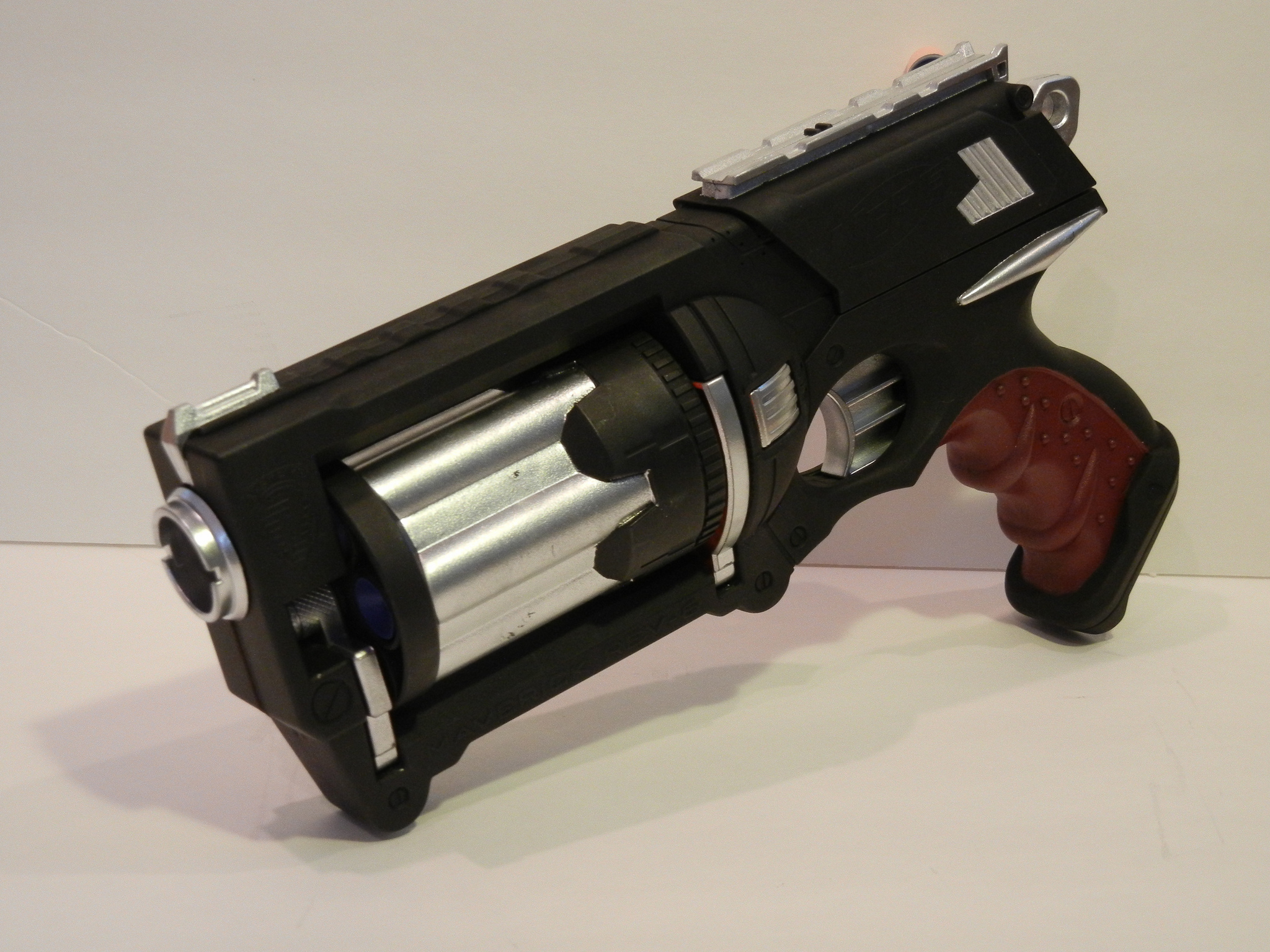
2.) heavy metal/blade runner feel (really digging this one and the wooden/brown handle on it)
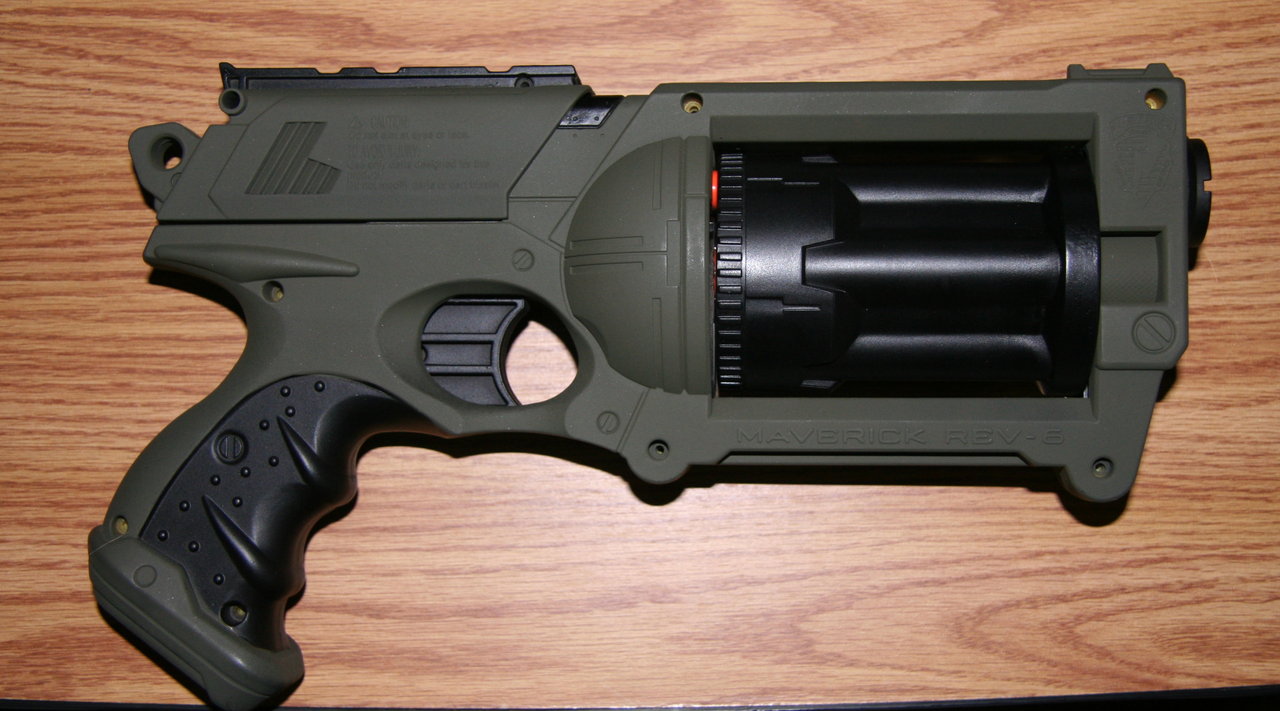
3.) Army green & black style:
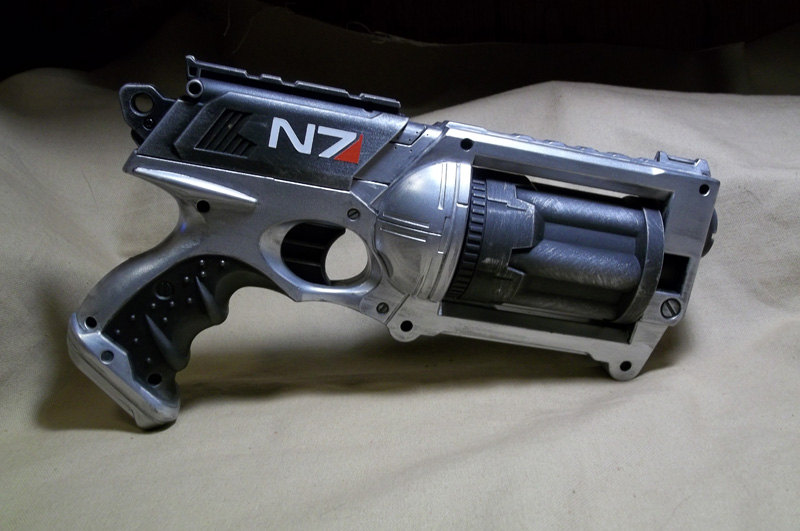
4.) silver & black (mas effect I think? not a gamer).. really like this style too.. even the logo (of some kind) looks right
5.) mixture, black, silver & brown grip..
Secondly.. a few other questions.. ![]()
1.) how important (cool points?) is that the nerf gun still works as a nerf gun? Ive been thinking of removing the working 'dart' aspect of it.. in favor of some electronics goodness instead?? thoughts?
2.) anyone else have a blaster project in the works??
-----------------------------[update after some work]--------------------------------
update.....
after some work.. I made some progress on this project. ![]()
I got the electronics all figured out.. (including making/baking/assembling the board, writing/finalizing the code, home brew/etching two additional custom pcb's...yadda yadda)
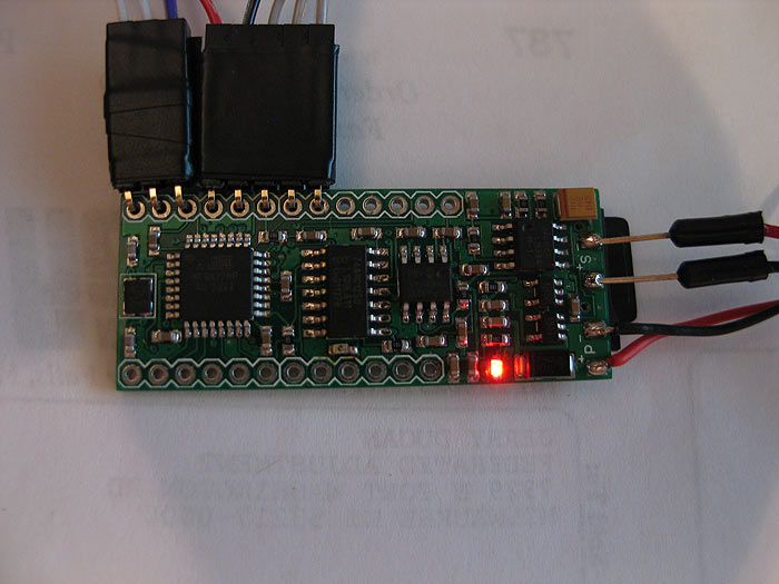
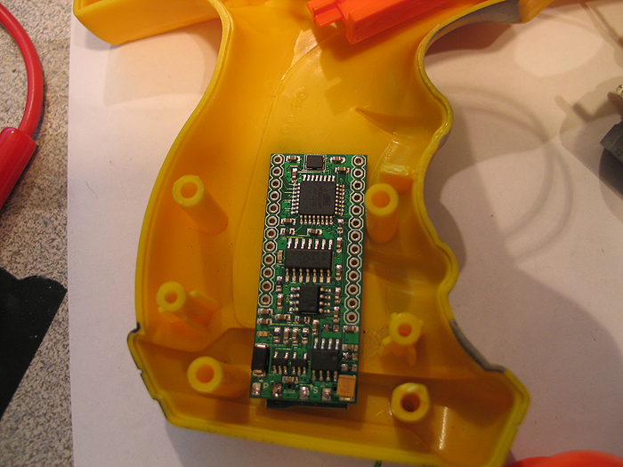
It is powered by S.C.A.B... ![]()
[kinda my generic/general platform for props..so far I love it]
I think I had posted pics of making my board somewhere before.. (in another thread currently running about)..
here it was it looks like:
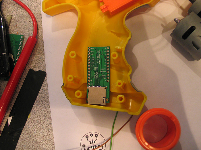
here it is on the left next to an Arduino board (with a WaveShield stacked on top of it for comparison)
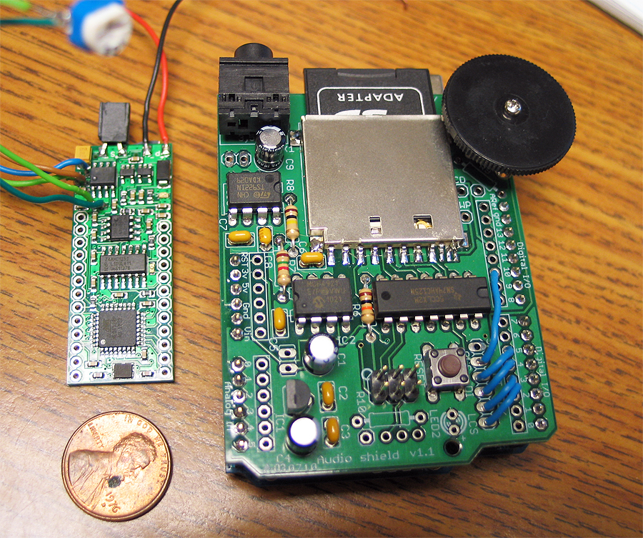
(fonts changeable on SD card, reads/loads a few defaults off a text file on SD card as well to set a few parameters on the blaster)
*safety = if on.. you need to have the trigger pressed when you boot up
*maxammo = total ammo count before having to reload
*acolor = led color when in auto-fire mode (can be r, b, or g)
*acolor = led color when in semi/manual fire mode (can be r, b, or g)
here is the first video of stage/phase one of the electronics and code development stage of it:
Prepping the nerf gun: (in no particular order)
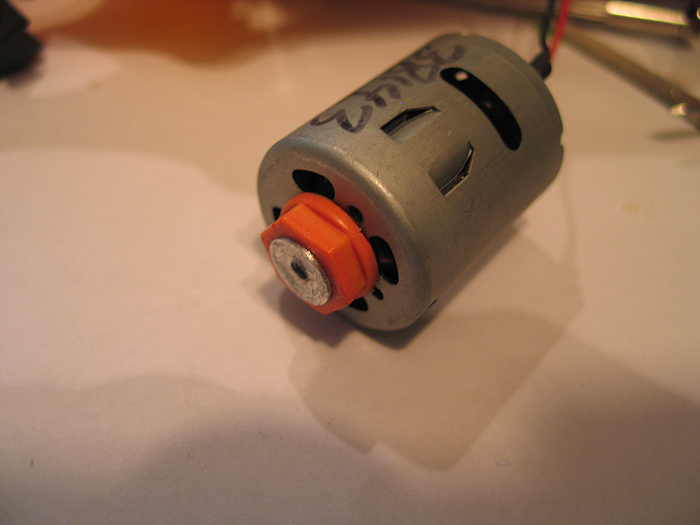
*I needed a motor.. but didnt really know how I was gonna make it all work.. about torque on motors...sizes..etc..
got lucky and scored a motor that looked like it would fit from my local science surplus store.. biggest I could find that was small enough to still fit..lol (it seemed like it was MADE for the gun once I got it home)
*I knew I need to somehow get some leds into the barrel.. and wanted to have it be RGB..
*Wanted it to reload by pulling the slide on top back
*Since its a blaster the SD card and batteries needed to be accessible without having to open the the gun up (ie: accessible sd card and re-charge port)
*Needed to account for a switch/button to switch from semi/manual firing mode to auto-firing mode
here was my first mock up for testing space and how I was gonna attempt things: (pre dynamic default loading)
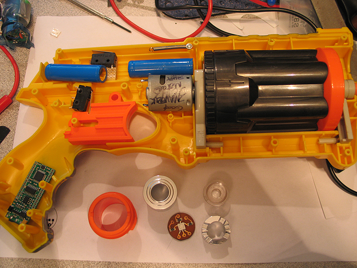
(s.c.a.b. in grip/butt)
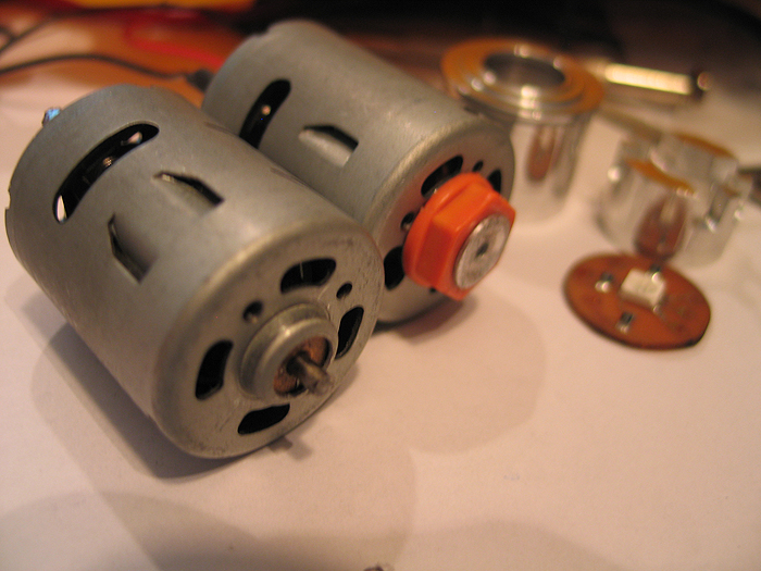
motor:
after taking apart the Maverick gun (many tutorials all over on it if needed).. I saw how the barrel was turned internally by trigger pull.. and figured Id hack/modify it to suit my needs.
I cut/sanded the hexed shaped top off the post/part that connected to the barrel and turned a little inner sleeve and press fit hole so it would attach to the cut down motor shaft.
before/after motors:
** what you dont see pictured is any pics of the custom PCB I etched for the components to drive the motor (SCAB/Arduino do not have enough power itself to drive high power devices.. so you need a driver/transistor...etc.. something to help out)
but here are the shcematic and pcb files I made in eagle for it:
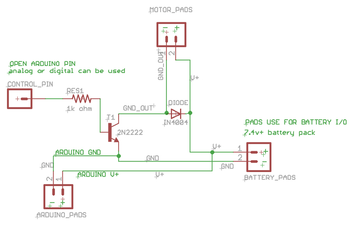
[img width=568 height=768]http://dmstudios.net/misc/motor_pcb/motor_pcb_2.jpg" />
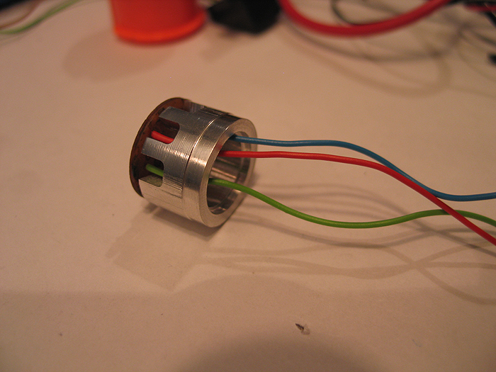
RGB barrel LED:
I was going to use a DX RGB led star I had laying around.. but then decided it was over kill for a blaster (not like I need to light up a poly tube/blade or anything)..
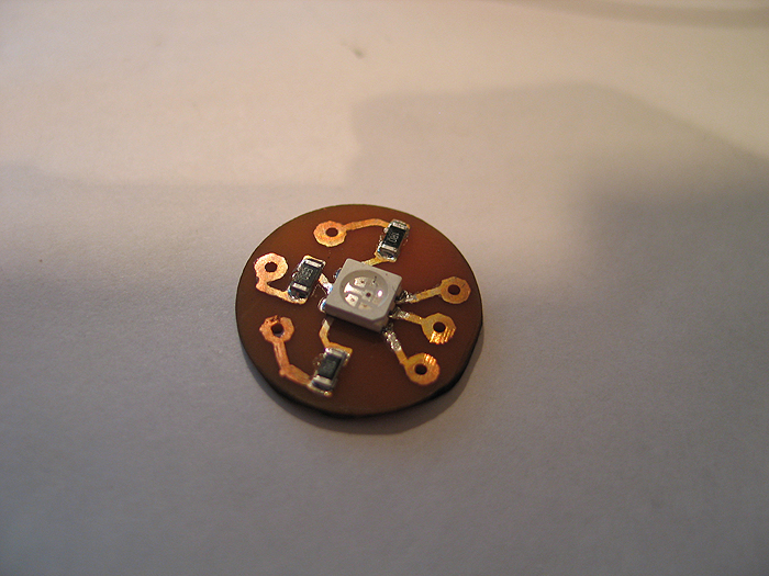
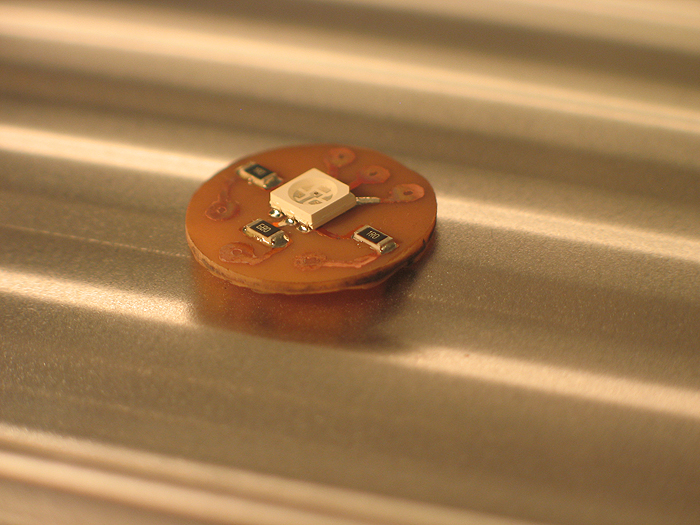
so I opted for a 505 RGB led,.
*created a custom home etched pcb for it
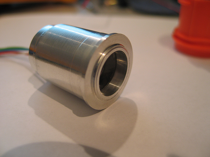
*turned down a two piece optics holder and pcb 'presser up againster' unit to hold everything.. (similar to Ace's small OD optics/holders... but mine are much more shitty and crude..and no threading....well you get the point).. haha..
I wont go into detail on how I etched.. I have posted a few tutorials stp-by-step on how to make these at home in 10 minutes enough..
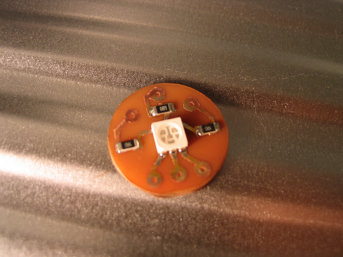
after etching.. smear some solder paste.. and populate board with resistors & 505 RGB:
bake it in toaster oven:
make inner sleeve/bottom portion to hold/push the pcb with (incuding some milled out section for wire passing)
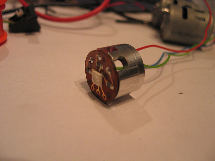
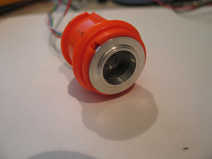
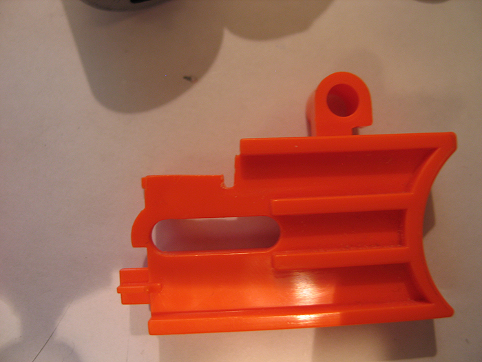
make outter sleeve to hold optics in it.. and also has the bottom portion slide in and sandwhich the pcb up against the optics......and fits in the Maverick gun plastic barrel part:
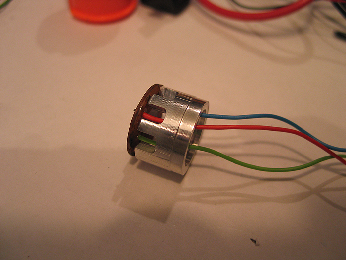
Unit all put together:
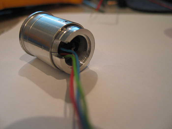
Inside the Maverick barrel:
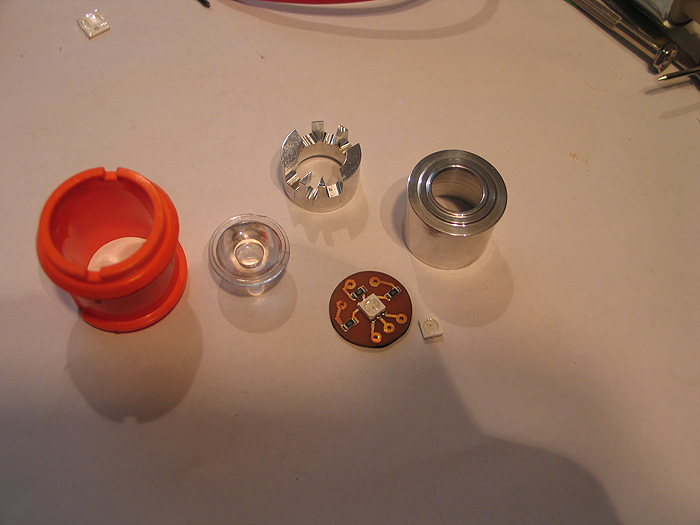
Exploded view of all parts/optics/pcb..etc:
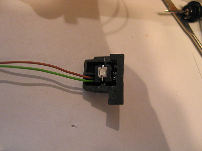
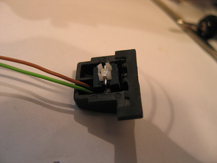
Switches:
Mode select switch.. had to think about where I was gonna put this.. without some huge, ugly slider switch somewhere.. that looked like an after-thought...
I eventually decided to re-purpose the same button/area that used to allow the barrel to swing out and reload the darts..
*(this switch has an led in it.. I am nto currently using it.. but could be used to have the switch backlit.. I have a 3.3v pad on the board)
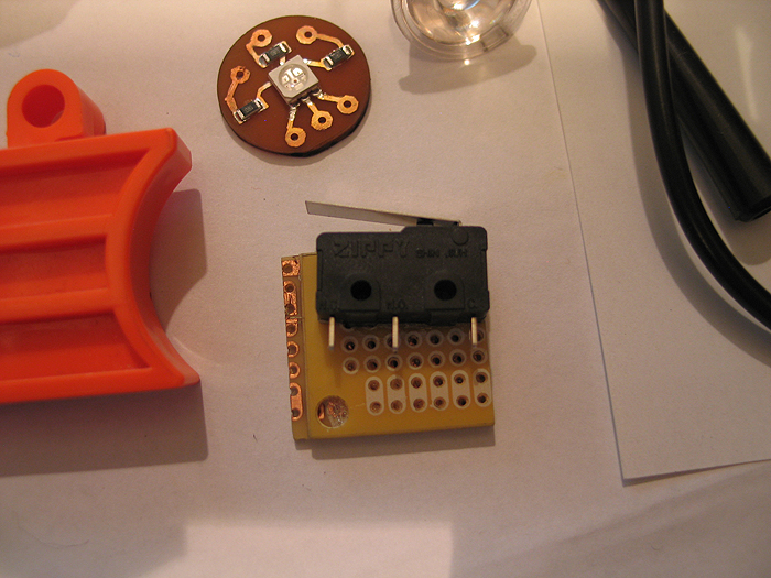
using a simple lever switch.. for both both main trigger and reload..
reload switch:
this one is secured to some perfboard cut to snug fit for inside the gun area.. it positions it in the correct place so the top slide hits it when pulled back, w/o mod to the top slide area/parts
main trigger:
you can see where I placed it int he above overview shot of the gun layout..
I mod'd/filed down the trigger a bit to hold the lever from the switch it in easier...(works great!)
after getting all this work and aligning things up.. I did a quick mock-up and cram-fu test with it mostly assembled.. (some parts have to wait for final paint and/or assembly)..
I took this video of its current state.. which Im calling 'done'.. and ready for break down and final paint & weathering (attempts) lol
thanks for the poll/feedback..
Im still not sure about trying a chrome/silver/nickle base and some dark washes.. or going with a black base..and trying to silver/grey dry brushing..etc.
(better decide soon eh?) lol
:005:
The Jeruino (Arduino compatible clone circuit)
Introducing the Jeruino! (not really.. but everyone else names their Arduino knock-off clone circuit.. figured I might as well be trendy too!) LOL =)
Everyone knows how much of a whore I am for the RFX platform...
I have also been playing with the Arduino for a while too... (any member here or JSSDC can easily jump in..with both feet and be up speed (at least my speed) in a day or so...so I dont wanna hear any pissin' & moanin' about things being too hard.. lazy I'll accept)
a HUGE problem for everyone who posts this junk is 'footprint' going from the non-practical BREADBOARD set-up that is great for YouTube vids.. but not so great for any practical project.. nor is stuffing a 'real/true' Arduino board into a project (they are more development/prototyping and have alot of bells and whistles you dont need in the end) very practical and wastes money.
you can get all the components for a barebones Arduino for around $7 bucks or so.... which is much better than $30+ each time to shove in a stunt or costume or other prop..
I saw Alec post his jedi training remote.. and pm'd him saying that is great project for an RFX or Arduino 'brain'.... since it doesnt need a CF or PC..etc.. this little brains fill a nice niche.
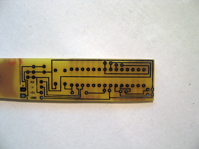
So I opened up photoshop and got to work on making [u]my[/u] first 'real' pcb schematic (IMHO).. since this was a real working board..and not just some traces to hold sensors or switches as I have etched out before..
(I etched another 'real' board...but it was based on TroyO's schematics for a multi-channel LED driver board.. which I've posted before...PWM chopper type)
this one I created myself from scratch.. and google/instructables... (basically ported my breadboard Arduino circuit to a PCB) with the intent being fore Alec's jedi training remote.. (anyways.. not sure if that currently being worked anymore) =(
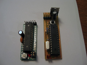
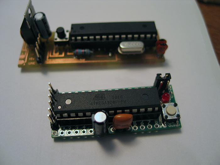
but I produced my first functioning Jeruino board.. ![]() (Arduino clone)
(Arduino clone)
Its no PlecterLabs, professionally design PCB.. etched by a PCB house...etc.. this is DIY at home... (so if your looking for that.. Alt+F4 is for you! =) )
anyways.. on with the story/post.. =)
SO I made a design in Photoshop to illustrate my traces and vias/pads..etc
you print this out on GLOSSY PHOTOPAPER.. done with a LASER PRINTER (not ink jet)
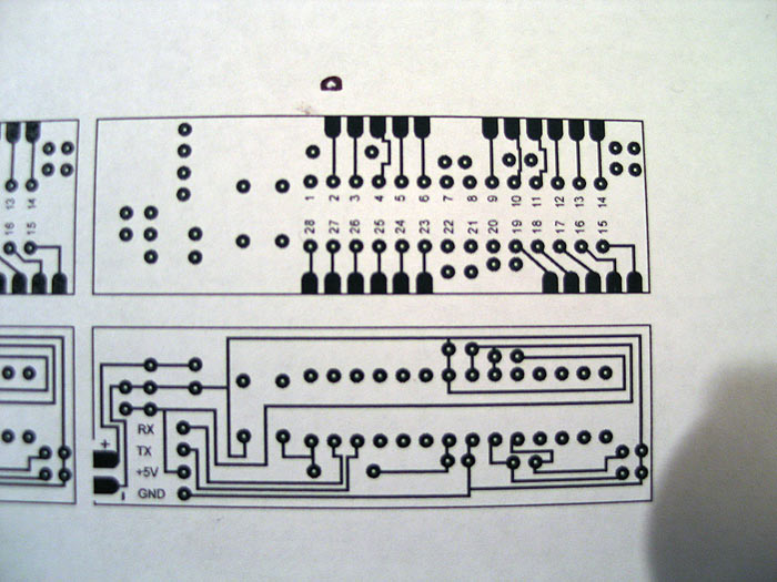
**this happens to be DUAL sided (avoid at all costs if you can..true PITA for DIY)
you cut out your traces/design... lay it over your copper clad board (RadioShack..or anywhere)
and you IRON it.. heating up the toner so it adheres and transfers to the copper board.
let sit for a few minutes.. run it under water.. and rub/peel the paper away under only traces are left on your copper board: (looks like you printed on the board... sometimes traces by the edges do NOT transfer good.. so be careful.)
cut out other side.. and get ready to repeat process:
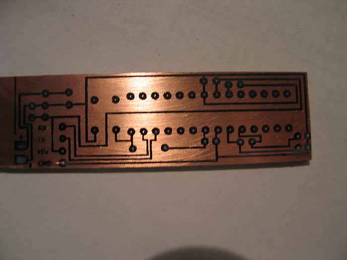
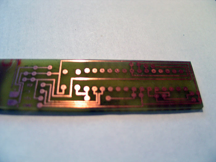
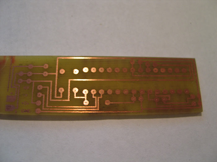
once you have your traces transferred to the board.. it is time you etch away the visible copper.
All copper is gone.. leaving only the traces you transferred to the board left.
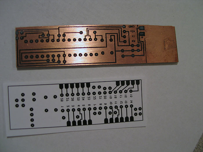
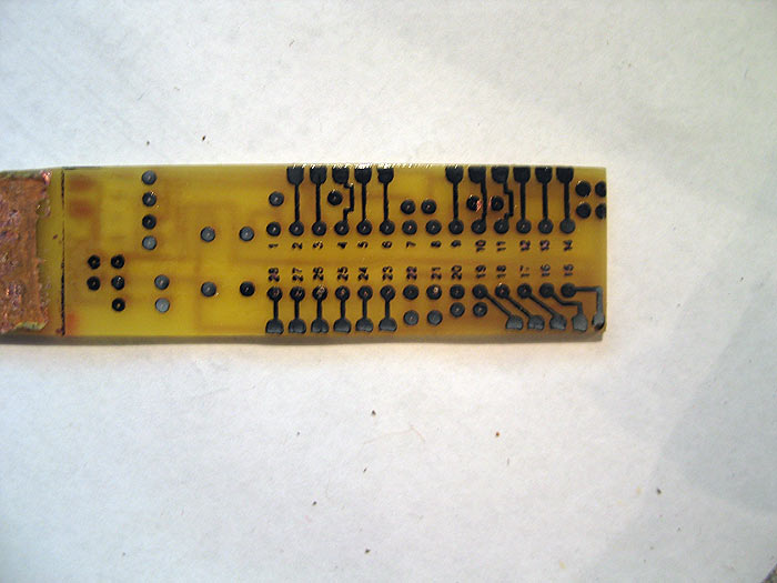
the flip side: (**warning..UGLY.. you can see the lift of the paper and traces that are crummy on this side) (you can see the holes mis-aligned a bit.. but no worries..all good)
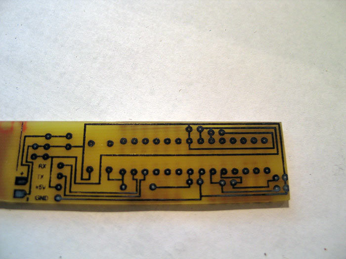
this side came out pretty damn good though:
from here.. I removed the toner on the board with some ACETONE..
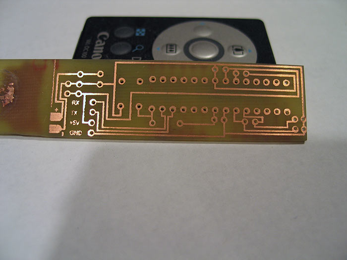
Next we drill the holes (damn there was a lot)
Doesnt look too bad (from the top)..LOL
clearer view of the bottom side with some mis-aligned holes:
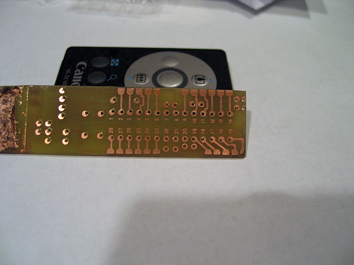
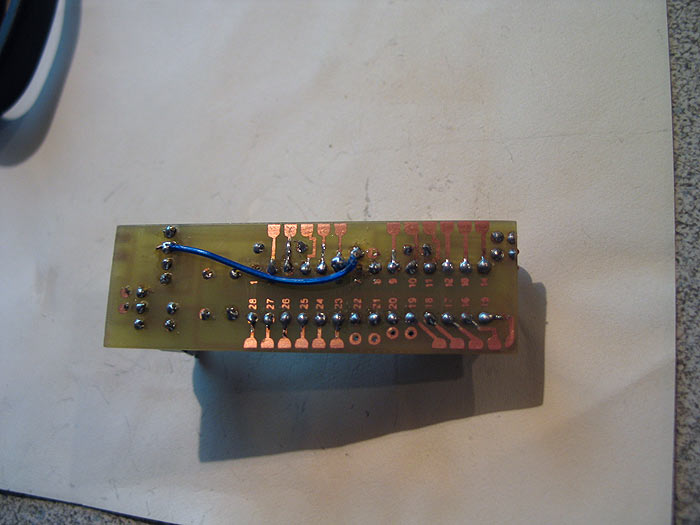
what stinks about the DIY approach with dual sided.. is THERE ARE NO THROUGH HOLES PLATED.. so its a real BITCH to solder through the holes to bridge continuity..
Anyways.. once you are at this point..
you can start to solder on your components:
and....viola`
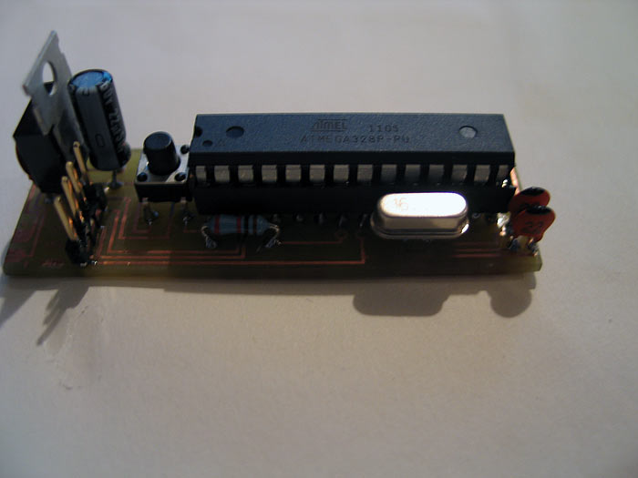
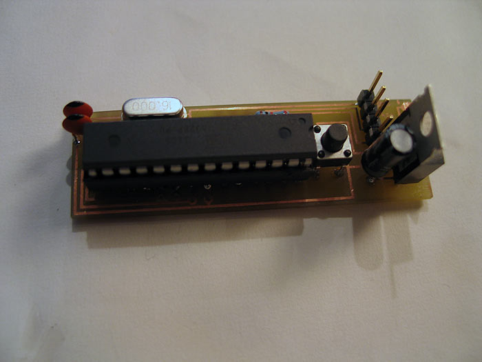
and finished product..
threw in a Atmel chip from my Arduino.. (already had a sketch/program on it..so I knew it was working)..
powered it up.. BAM.. it worked! (STOKED!)..
however.. before I posted.. I needed to check the FTDI headers.. (these 4 pin headers are how you talk and upload new sketches/programs to the chip to be 'run')...
[b][size=150]FAIL![/size][/b]
it runs...works.. but only a pre-programmed sketch that was/is on the chip.. (BOOOO!)..
who wants to buy a REAL Arduino (besides people like me).. just to swap out the chip for your final project every time your done? (I guess many people do it this way though..as FTDI takes up a little space?)
be nice to just write directly to your final Jeruino.. ![]()
so after some BS and a few swear words.. I fixed everything..(ala Ultra Sound approach) LMAO...
found a few continuity problems from top-side of board to bottom side of board..
and an FTDI problem...
the Ultra Sound fix was a missing trace to a certain pin (pin7...VCC..yikes)..
so I had to use a fix wire..like the old US boards.. hahaha.. (throw-back)
(it looks worse in the pic)
and of course.. because no good deed go un-punished and hard work is always laughed at in life..
I got punished by NOT doing my due diligence.. doing all this hard work for NOTHING!..
as I found a KIT.. that does exactly what I just created from scratch, myself.. that is MUCH more easier, and much more professional (however you dont get the satisfaction of failing over and over, swearing alot....and its missing any kind of Voltage regulator.. but making a quick PCB for that would be no problem!!!! haha)..
so I got a kit to compare mine..to 'his'... (fucker.. I really like his kits!!)
so without further ado..
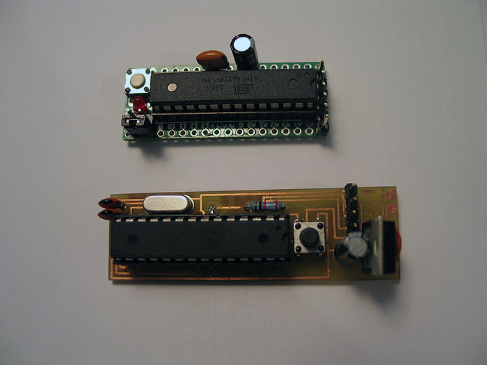
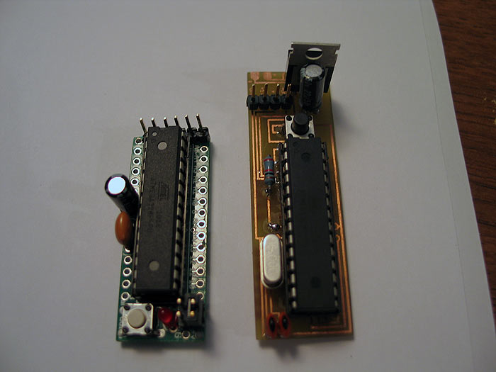
some compare pics:
my DIY vs purchased (mine has a vRegulator though..so its a bit longer)
**disclaimer-
I make no implications that I know what Im doing..
that this is the BEST approach
that this is absolutely how things much be done.
I am simply sharing what "I've" done...
but for extra $10.. it can really kick up a stunt or costume..
you have a BRAIN with MANY I/O ports to hook stuff up to..
LED's... servos/motors.. accelerometers... and the list goes on and on..
all the same brain.. just change the code. =)
hope this helps someone finish that special prop/project.
feedback or questions are appreciated.
Thanks gang..