Custom 7-piece smd led bra graphs (and assembly)

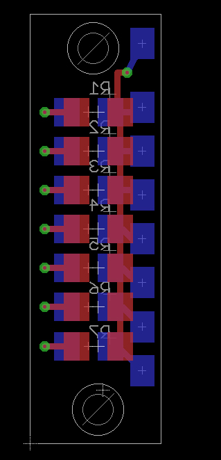
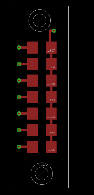
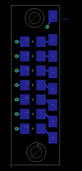
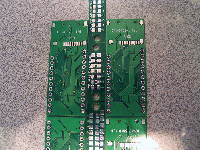
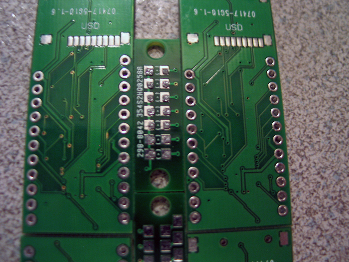
From the JSSDC run Austin put together.. the bar graph pcbs..
blue is bottom layer.. red is top layer...
Here is link to the Eagle files too:
http://dmstudios.net/misc/led_barGraph_pcb/led_barGraph.zip
you can take those.. and export GERBER files for the fab house..
I already checked the design against the iTeadStudios design rules..and everything passed.. (so should be good to go)..
that being said.. it doesnt save us from ourselves! look at..study it.. make sure its 100% right..
walk yourself through the assembly and the application of using it in a build..etc.. see if you come up with any troublesome area...etc
I think one that fits/works in the MHS activation boxes would be nice.. same hole alignment..etc..etc.. some standoffs.. done.
if you choose to use the resistor pads on the CF.. bridge the pads on the bottom of course
suggestion.. if you plan on either offer built ones.. or making several of these for yourself..
invest in a stencil!.. (at least for the top [led] side)... its easier than you think to do... (costs a bit of extra money though)..
but saves time and produces a better 'finish' for your components/solder than doing it all by hand..
I have used both pololu.com and ohararp.com (I think thats the right name?)..
I preferred the later.. as it comes on a piece of KAPTON vs MYLAR.. and produced a better stencil (and Ryan was great to talk too.. very helpful for us noobs)
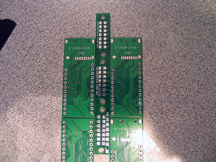
thats the nice thing about getting pro boards made.. you can use both sides to run traces way easier than a DIY board..LOL
----------------------------------------------------------------------------------
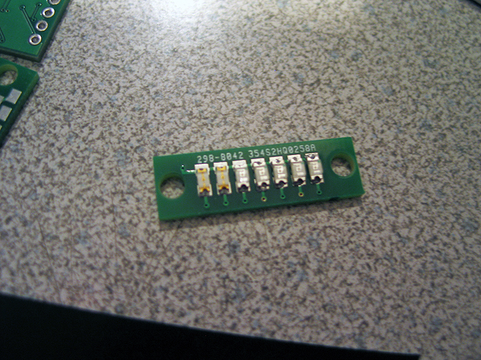
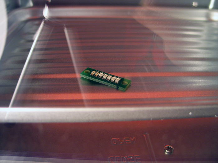
my attempt at assembly:
here are some pics of the board I just did this morning..
(summary)
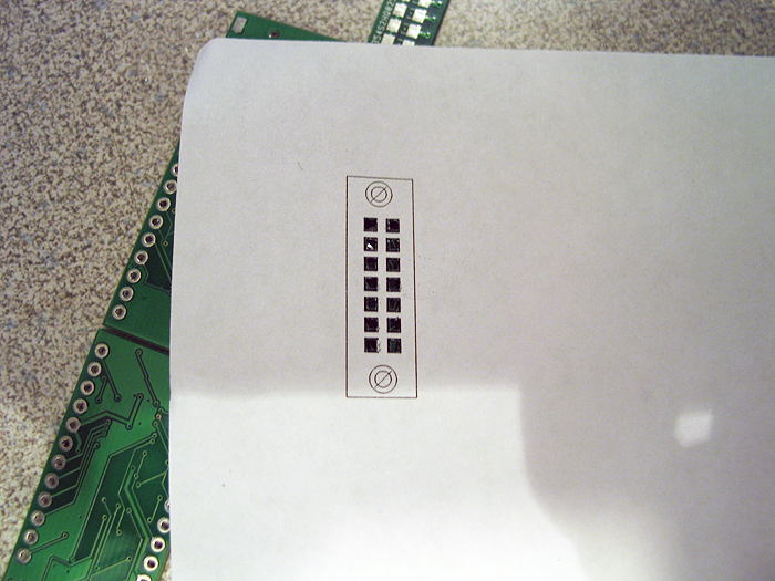
1.) print out the pads/footprint from Eagle to a piece of paper..use exacto knife to cut out pads (ie: make your solder paste mask w/paper)
2.) align your pcb with enough, equal height stuff around it so the mask doesnt 'bow'..and you have a bigger surface to 'smear' against.
(I just use extra/leftover pcbs and stack along the sides)
3.) take your paper mask, and lay/secure it over your target pcb
4.) smear some solder paste at the top of the 'mask'... and grab a credit card or something like a putty knife.. and smear the solder paste over the mask
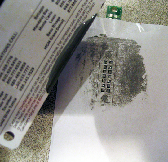
5.) for this type of PCB/project it doesnt have to be 'perfectly' aligned on the pads... (for fine pitch components.. I would wipe it off and start over)
you can see the alignment isnt perfect.... but it doesnt matter here.. also the heat will pull the solder toward the pads and even it out..etc
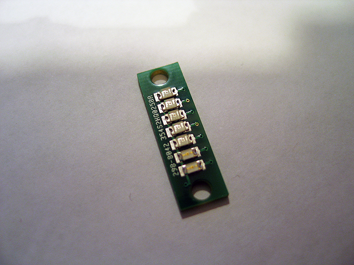
6.) after you apply your solder paste, you can populate the pcb with your leds (align/straighten as you see fit)
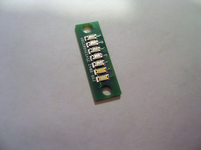
7.) throw it in your toaster oven...(tick tock)
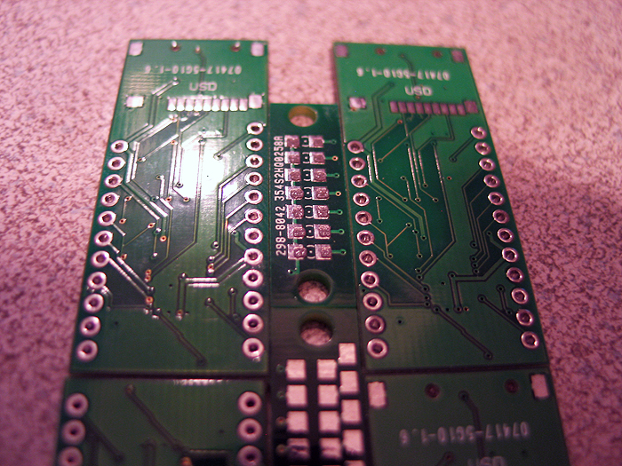
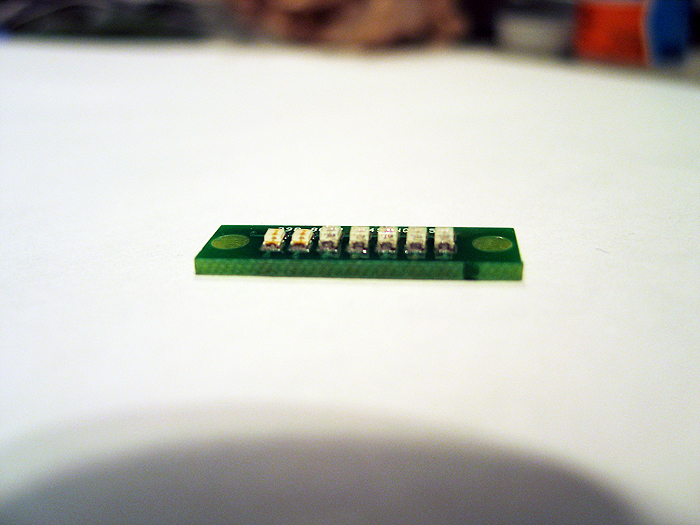
8.) all done:
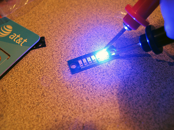
I didnt do the resistors.. if I was going to.. I would have started with that side first.. then done the leds last.. (or just did the resistors by hand.. as you dont see that side) ![]()
all-in-all.. it took about 11 minutes to complete..