Joe Jedi Control Box Use: 2

Im always looking to re-use or hack existing parts.. MHS.. heatsinks..whatever..
I had originally played with these control boxes and mounting a PLI in them (dimensions are almost spot on)..
I never have any 'cover' on them..and they looked a bit 'steampunk/unfinished'.. (not the type of fit & finish "I" like)..
may a few.. and was done.. other day.. got back to working on one for a buddies MHS OBI I am making him.. (no clamp.. just this contol box)
I figured Id share for a few reasons..
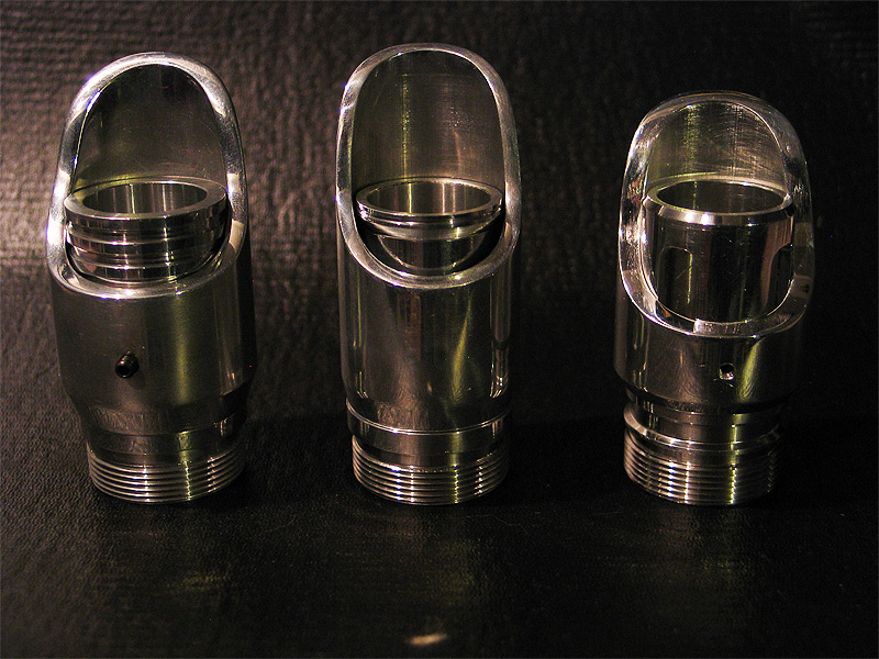
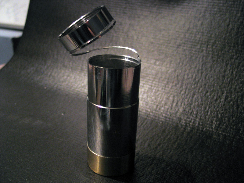
1.) it actually came out fairly good.. I made a black one and a 'brass' one..
2.) anyone can make these..no special equipment needed
3.) makes use of old or existing 616 parts..
4.) total was really only a few bucks. (@ your local ACE hardware..some brass flat .99 ..and a 'brass channel' $2.49)
this may get a PLI mounted in it as well..
and the cover will get a slit/slot cut out in it for the leds to shine through..
alternatively.. you can put fill in the sides where I am mounting switches/buttons.. and keep the space under the cover blank/empty for switches..
"OR" see the GHETTO PCB 4 U thread..and make/etch your own PCB and fake resistors and diodes..etc.. and mount in it there..like on the OG graflex's
(and I also posted a pic of an OLD AoF pommel I had two of..that I modified.. and added in some 'rubber grip' pieces..
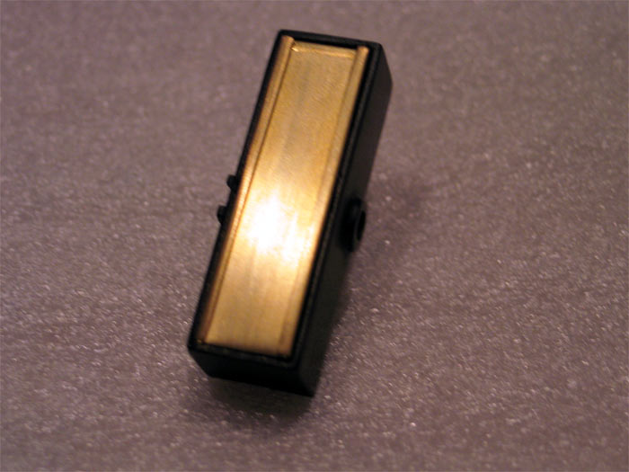
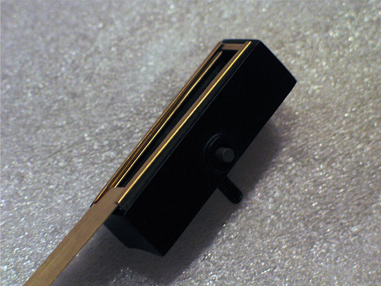
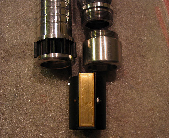
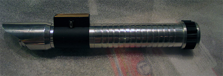
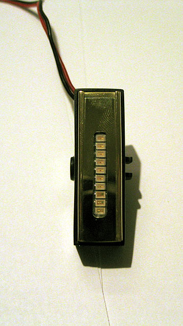
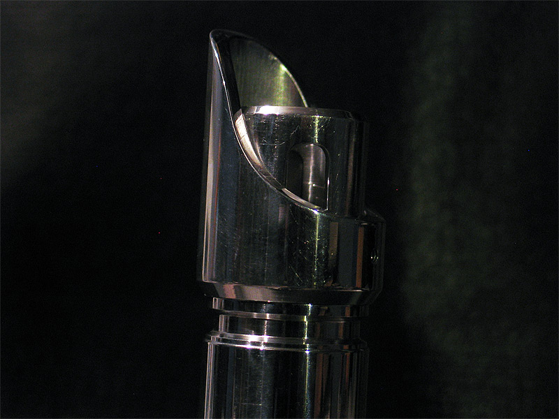
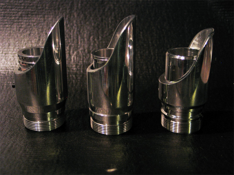
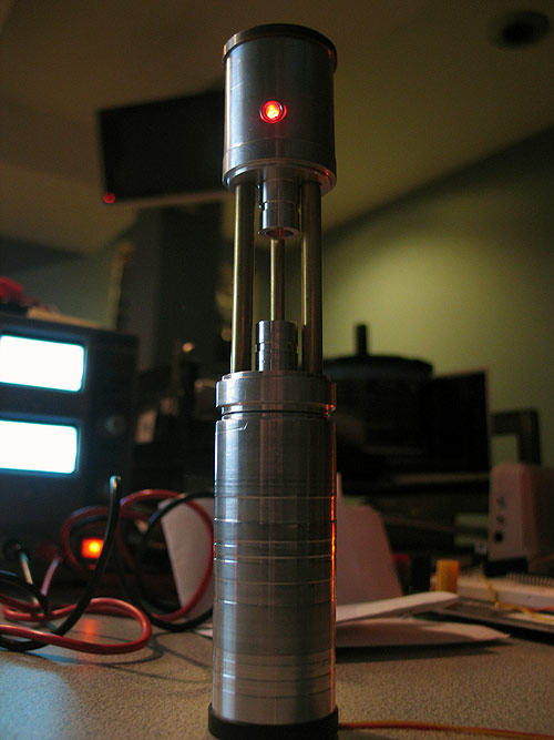
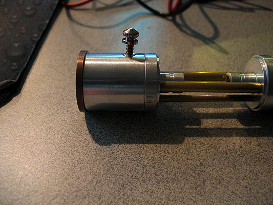
Front.. close cover:
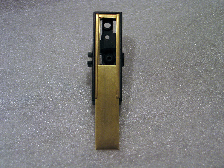
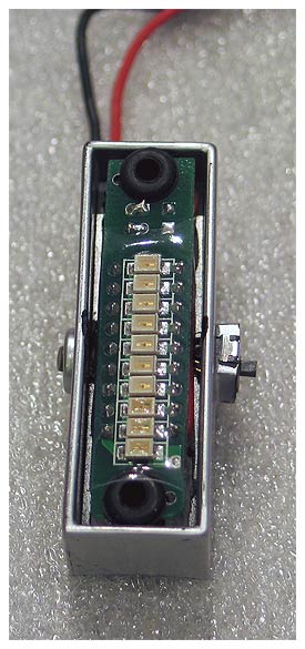
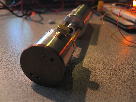
Top cover open: (bottom has holes to run wires) (you can see both slider switch and mom. switch on each side)
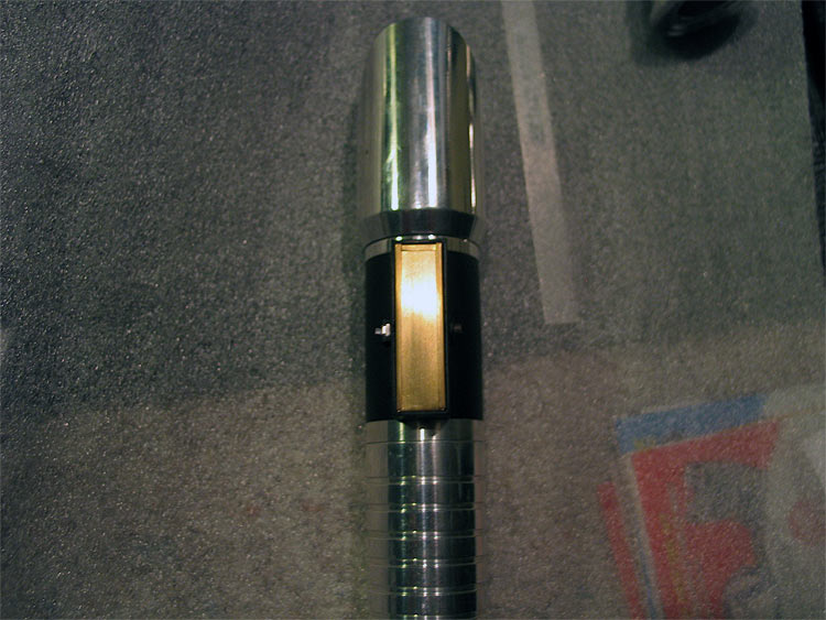
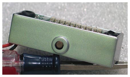
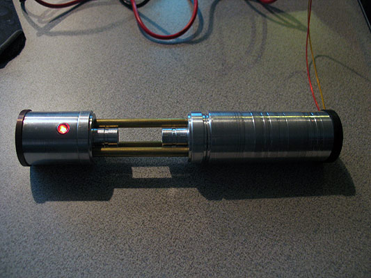
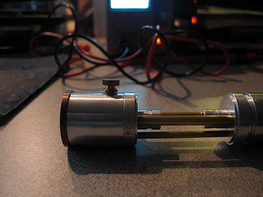
Side:
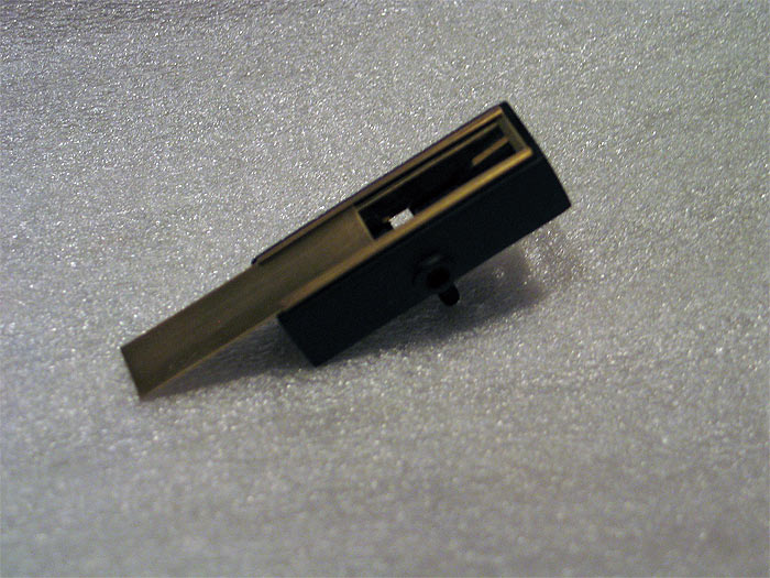
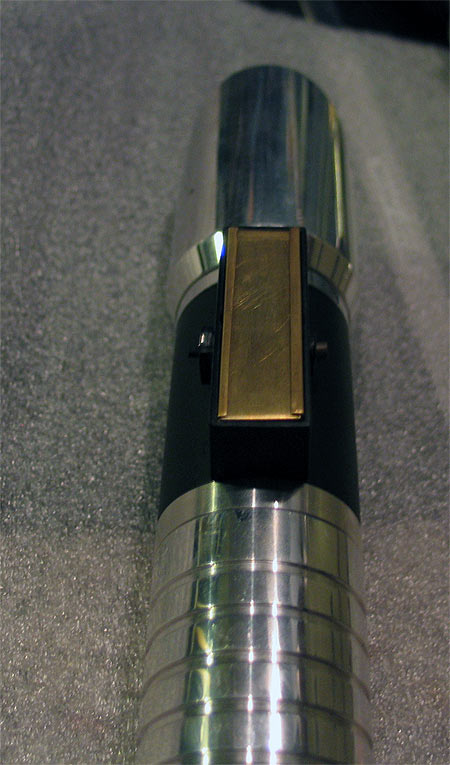
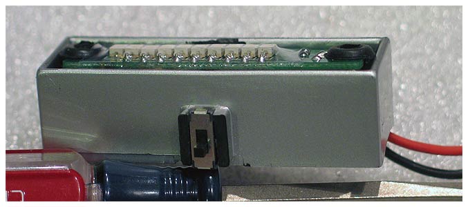
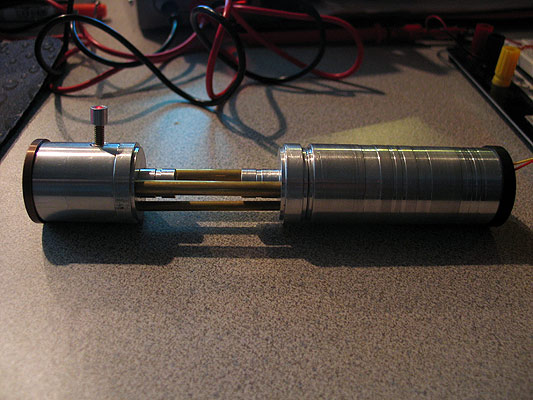
Slider Switch side:
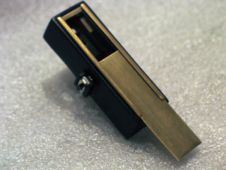
Mom. Switch side:
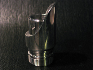
AoF Pommel mod:
Since I have a few of these.. I have some without the switch stuff cut out..
but I was thinking the slider switch will be for the PLI...
*always on (unless kill key is in of course)
*off
*on when saber on
Be cool to fit in battery in there! pop it out to charge it up..pop back in!..
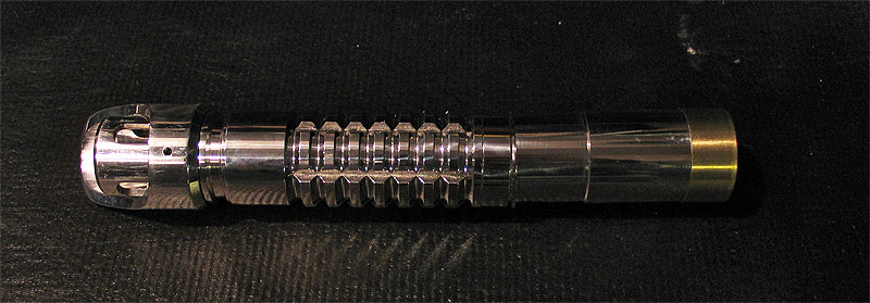
anways.. this thing is a space saver fits on the outside of a 2" extension piece..
single (middle) point mounting, means no worries about using it at top under a bladeholder/heatsink ![]()
feedback is always appreciated.
Thanks
-----------------------------------------------------------------------------
oops.. the pics..
-----------------------------------------------------------------------------------------
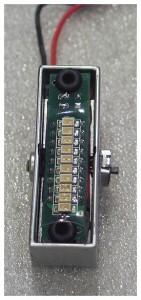
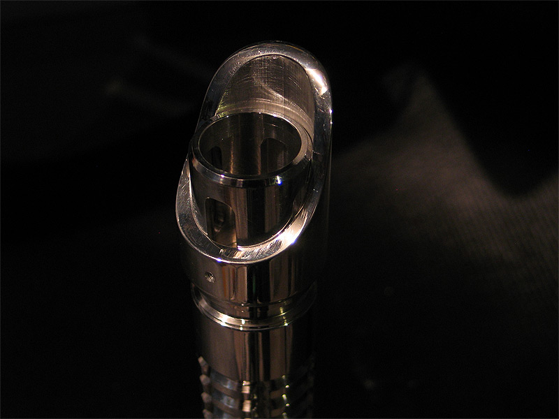
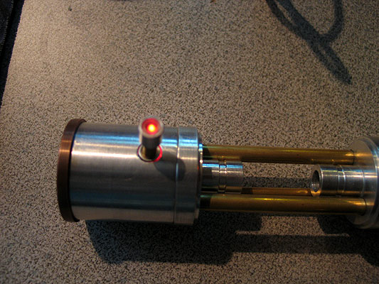
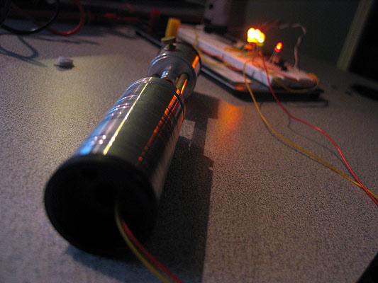
also...one more last pic... before final steps are done..
quick mock up of the PLI inserted..
not fully installed..(you can see the wires still)..
but you get an idea of how it'll work & fit.
you can also see the new 'cover' I am making for it.. to let the leds shine through..
--------------------------------------------------------------------------------------------
I think I might have to re-do the sides (again)..
the problem at hand is how to get the PLI to sit a bit LOWER in the box..
I have a few options..but none will really gain me MUCH more space in lowering it..
alternately..re-doing the sides and making them a bit taller would work.. but will it throw off the visual looks of it with it being taller and not 'as' flush?
anyways.. anyone/everyone can make these..
takes about $4.00..but you should be able to make 2 out o the materials..
At my local Ace Hardware store.. (just like everyone else).. we ave a little Brass/Aluminum/Copper section for hobby metals..robs, tubes...flat/sheet...etc..etc..
one of the pieces they have is RECTANGULAR tubing.. not very wide at all..but a few random sizes..
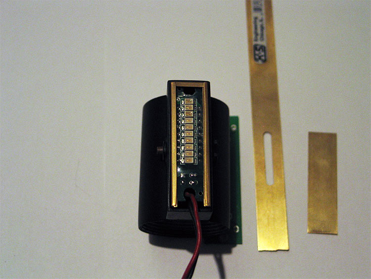
I grab one of the bigger pieces..and then the FLAT brass strip you see in the pics..
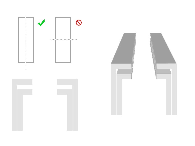
cut it long ways....and down the 'vertical' axis..not the horizontal.. (see pic)
you'll be left with two pieces like this:
_ _
| |
| |
| |
| |
- -
you dont need the bottom 'lip'.. so shave/and it off... so you're left with an upside down "L" shape:
_ _
| |
| |
| |
| |
thats basically it.. LOL
make another set just liek this.. but make them SHORTER (not as tall).. so just sand/shave down MORE wen taking off that bottom lip.
this is the basis of your 'shelf' system.. so you can slide the brass cover into place..
_ _ _ _
| - - -- |
| | | |
| | | |
| | | |
you can then do the same..of course smaller width.. for the 'width' of the box..and to keep the 'sides' secure and not loose.
---------------------------------------------------------------------------------------------
ok.. to finsh it up more or less..
the PLI cover/cutout window..
my question to you guys is:
to secure the PLI...
should I:
a.) try and use some screws/bolts to lock the PLI down?
Id of course like to do this UNDER the cover.. but if not..might have to go THROUGH the cover.. ending the removable/sliding aspect of it.
b.) raise the sides a bit to compensate for the 'thickness' of the PLI?..then I can mount the PLIS down.. glue or secure the sides in.. and the cover can be removable?
sorry about the finger prints.. did a quick buff on the pieces to take a pic for YOOUZZ GUYZZ..
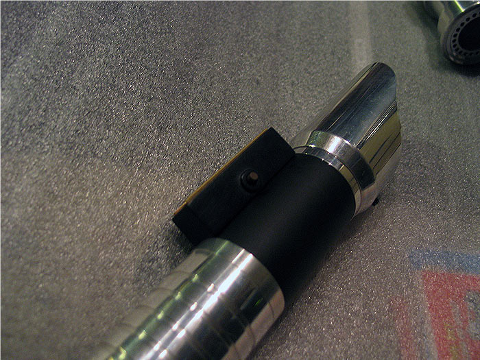
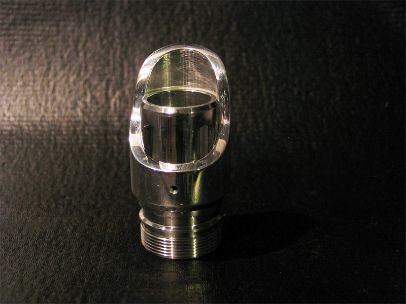
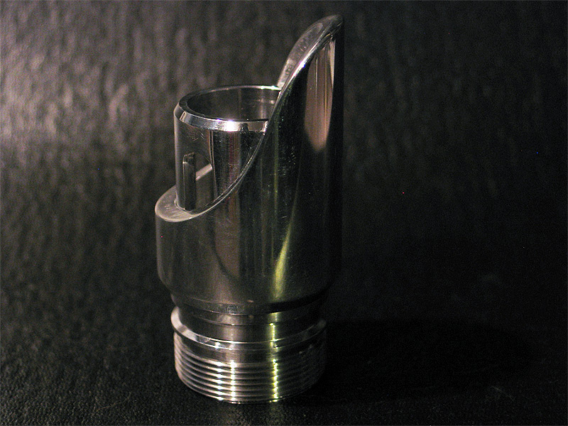
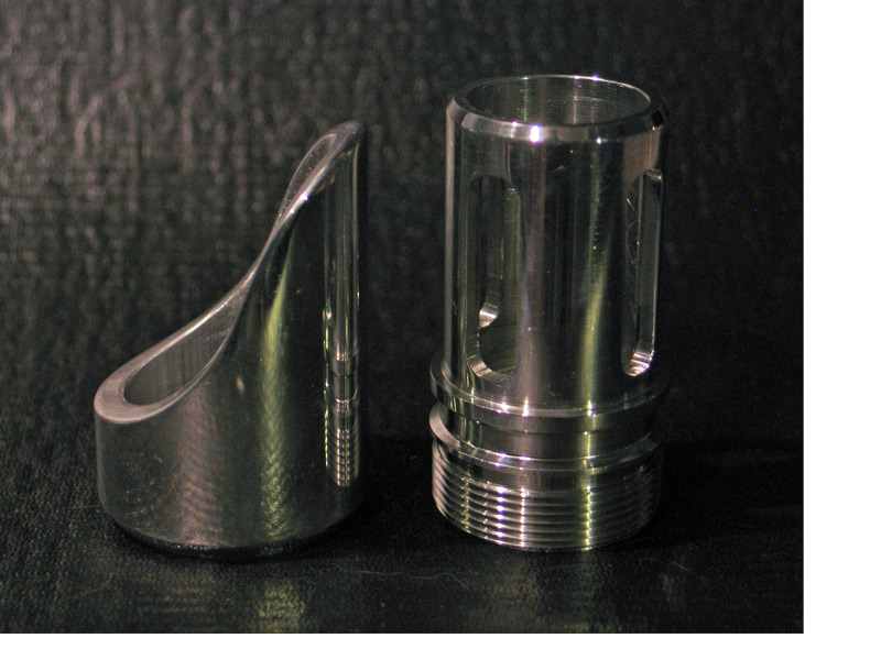
Joe Jedi Control Box Use: 1
I have been working on a few PLI housing/control boxes for some of my builds..
figured Id share the latest mock-up/model with everyone.
this isnt perfect..but its a mock-up.. I have a few that turned out nice.. black & silver also, with & without 'bands' style..
uses the PLI from the store.. and fits perfectly..
mounted a mini latching slide switch (DPDT) for the main power..
on this particular pictured...(since I am testing out a layout to be used with a Plecter Dimmer) sports a momentary tactile button on the other side to set the options of the board without having to be 'inside'. ![]() (personal preference really)
(personal preference really)
but could be anything, or used for whatever AUX you like.. instead of a slide switch I have also mounted a few momentary push buttons in that area.. with some 'covers/caps'' (they look nice)..
what you dont see pictured is any covers.. still working on a few.. nothing Im super stoked on.. the LEDS are off-set and not centered.. so its hard for me to find a balance in the cover design with what I have found so far. ![]()
My idea is always to make things FUNCTIONAL and look clean/smooth in all my designs/builds.. this lets me house MANY things without much worry about where I need to drill holes in my MHS parts...:) its just one whole to get all wire through.. the hole on a pre-drilled hilt is plenty big for example.. ![]()
I have also made other version of this that DO NOT have a 'real' PLI.. but in fact just a strip of colored LEDS.. (looks great..but is just eye candy/accent LEDS).
I was hoping Jay-Gon-Jin would have come up with some thing like this on those brass runs he did.. they were sorta close.. Also surprised there isnt any 'parts' like this available in the store or other 'outlets'..
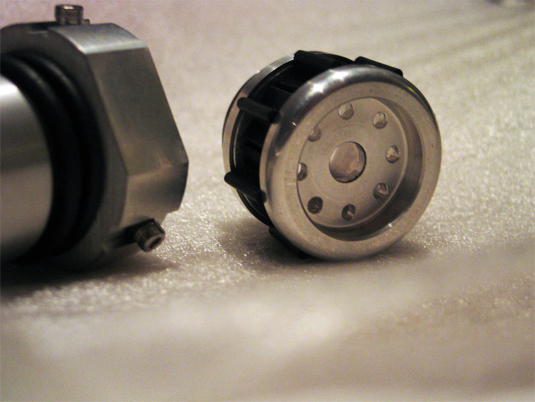
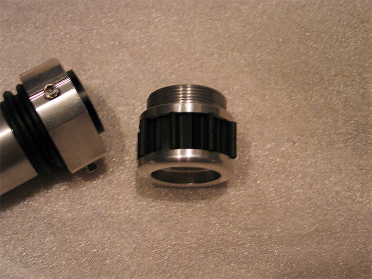
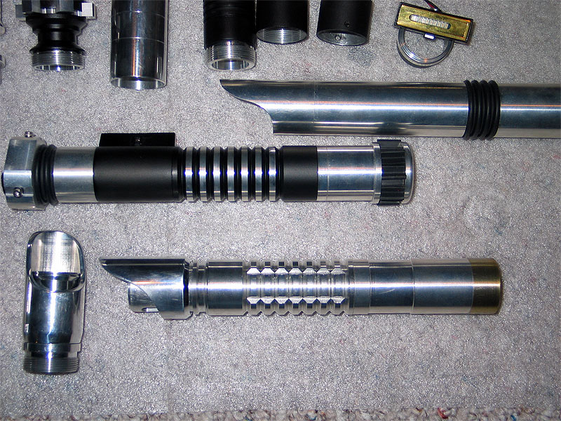
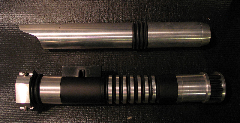
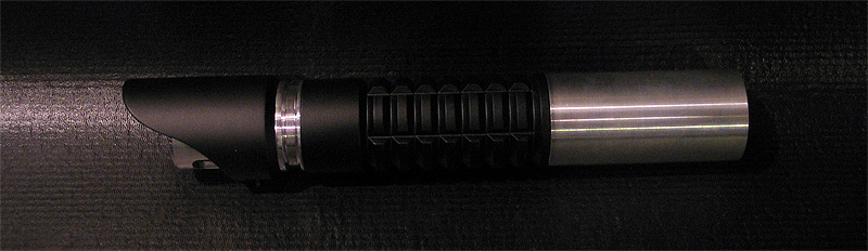
Custom MHS BH #3:
I posted asking a few questions on PC'ing..
this was inspired a while back from Big EZ's Tactile build.. (which seems to have been a trend lately)... but was supposed to have a 'trigger guard' built in..
it does.. but Im not 100% happy with it.. (taken from a toy gun from my kids).. looks 'ok' after paint (maybe better)..
I have one more guard I wanna try (hoping it will fit better or a mount solution will reveal itself to me!)
anyways..
here are some pics of the WIP build..
modified BH
custom shroud
v-groove
3" extension (modified)
stock MHS pommel
I also fubar'd my 3" extension.. (pics below)..LOL
so I need to grab another off the bench and mod it again.... goes to show.. do NOT PUSH the amount you can turn down an MHS part! (especially by the threads!)
anyways.. figured Id post a few pics.. and what NOT to do to your MHS parts! LOL.
before I messed up the 3" extension:
Broken piece in place:
all three mod'd BH's with custom shrouds (3 so far...and I think last..I have 3 'longer' versions that are similar to a 'graflex' top in length (not quite) that go over not only the BH's..but part of the main body as well..... too bad it'll be seen as a rip of Slothfurnace graflex build that uses it...cause the firstone is very similar.
some other junk too.. my first red/sith build (bottom)
and an attempt to make a 'clean'.. future'ish saber.. very clean..nothing but liquid chrome 'look'.. (working on the MC type buttons..but a bit more 'recessed'
and my mistake: =(
any thoughts or ides on the trigger/guard is appreciated.. Im really NOT digging using plastic or salvaged from a toy.... but not sure what else?
-----------------------------------------------------------------------------
I PC'd it..
as well as the v-groove..
still on the fence
1.) do I remove the PC from the 'ribs/nubs' on the v-groove? (and pc them trans gold?)
2.) do I do everything that is in bare aluminum in trans gold? (nubs and BH..and pommel)
keep in mind the 3" exntension is there as a filler..cause the other one broke.. needs to be turned down still.. and some visual mods/grooves added..
that will also be black.
suggestions on 1 & 2?
sorry only one pic ATM... the others were kaka..
xCore: #1 (HAL)

I dont think I ever posted these (I didnt see them at least in this thread)
I expanded on my 'xCore' (cough cough)..lol..
to make in more like others (Goodman, Big Ez commented on..etc..etc) about making the 'core' a stand alone unit..
I tried to make it generic enough to work as many build as possible.. (chokes etc..probably wont work without custom install & wiring..)
I made a couple like this where the battery pack, crystal chamber, LED & switch housing is all on unit.
I can fit 2AA & a USB board in the battery compartment, behind the speaker....so speaker, battery & US board.. think of TCSS all-in-one sound system with a 'sleeve' over it..
I went for mounting the switch as HIGH as possible tot he LED as I could.. about 1" down from TOP of led heatsink )a lot less from bottom of heatsink)
the 'crystal' stems/holders both were made to hold 3mm chrome bezels from RadioShack.. the backs are count ersunk to hold nut and screw in place to lock.
so each one 'can' have an led in it same color, different colors.. RGB accent leds..etc..
I dont have any crystals yet to play with..
but the led holder stems will be cut down (faced) to make them a little smaller....as well as the brass rods/threaded rods.. to match whatever crystal I end up using.
right now I think its about little over 1" long crystal room..
after final cuts, it will be around 6.5" I'd say..
these were all rough cuts, eyeing things up for the most part.... using junk/crappy jigs..
once I get some measurements, prototype results..I can make some nicer ones sanded and polished..etc..
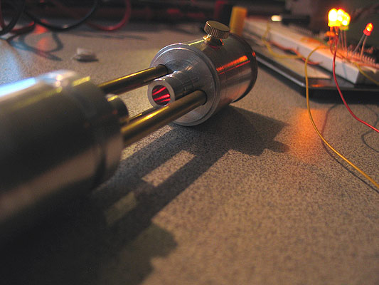
switch is illuminated switch of course..
you can see light here..
checking out different 'stems' and switch caps/heads... most have hole drilled in shaft to let light through..
most of the sections are 'modular'.. and can be broken off from the 'main' core (if you will).. to work with specific saber designs..
all of these of course take advantage of the MHS 'locking' feature for the speaker and/or the heatsink..
I 'piggy' back off one of those (depending on the saber design and the core design).. and use that part to lock & secure my whole core down.
in these pics.. they are actually in-accurate.. that is a stock width speaker holder I am using..
however (unless I measure perfectly).. because I am using the heatsink to lock my core down..I need to turn down the the OD of the speaker holder...so it can fit inside of the hilt body...
the holder needs to be turned down 'slightly' t be used with the sleeve/bucket.. but the OD needs to be turned down more for it to fit into a MHS hilt..
wiring is tricky..you can only get some many wires up the small 'false tube'.. I think I got 7 or 8 up there..small gauge.
and getting 2AA and a US board in there..take some serious Eastern cram-fu. but it works.
I think I can make that small OD false brass rod a bigger (normal sized) one to allow for more wire room.
anyways.. its pretty clean wire wise. all hidden.
some decorative lathe & mill work on the parts/sleeve and they could be pretty slick looking.
feedback appreciated..
thanks