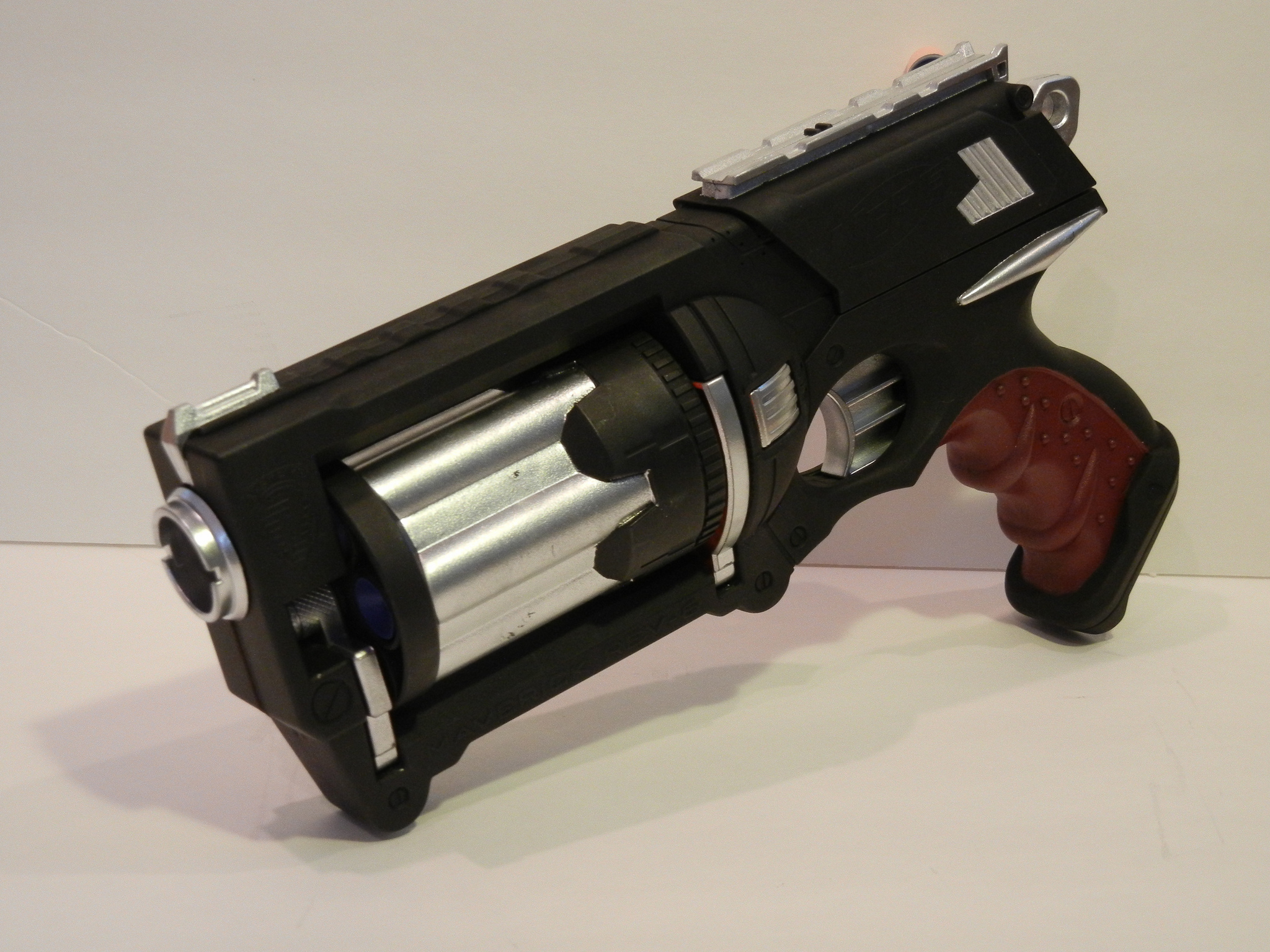
Maverick (Nerf) Mod: custom blaster build log

Looking to do a Nerf gun mod... wanted to get some feedback on how to paint/weather it..
found a few projects on-line that I thought we pretty decent.. trying to decide on my own direction here.
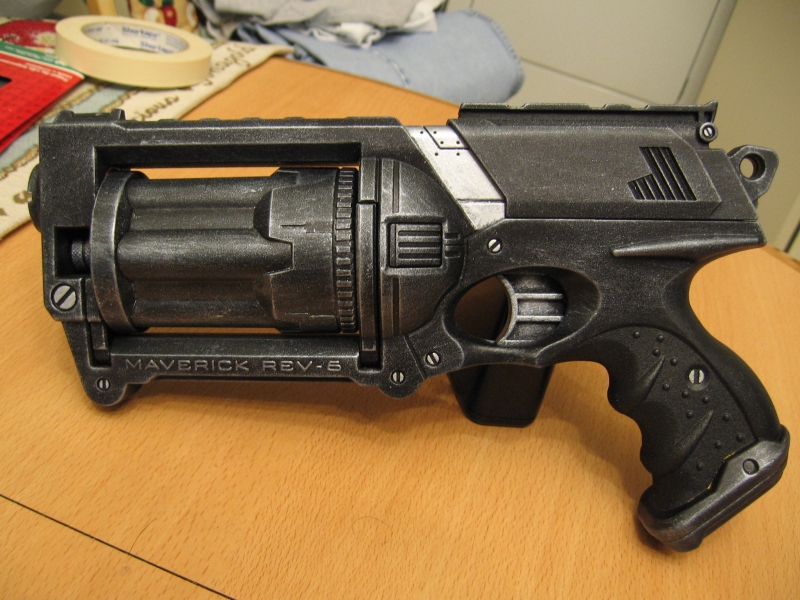
1.) black & silver based (techy) theme
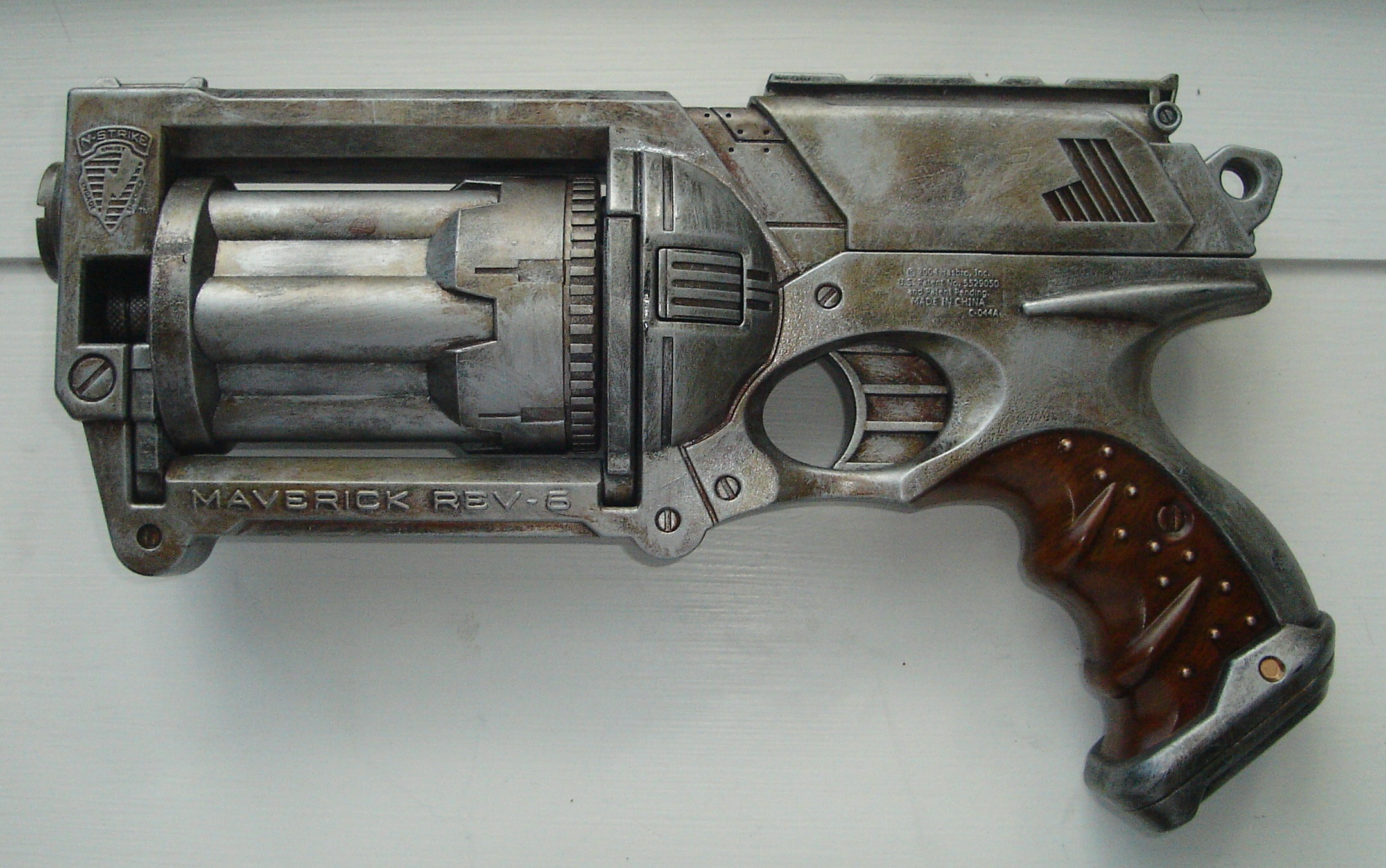
2.) heavy metal/blade runner feel (really digging this one and the wooden/brown handle on it)
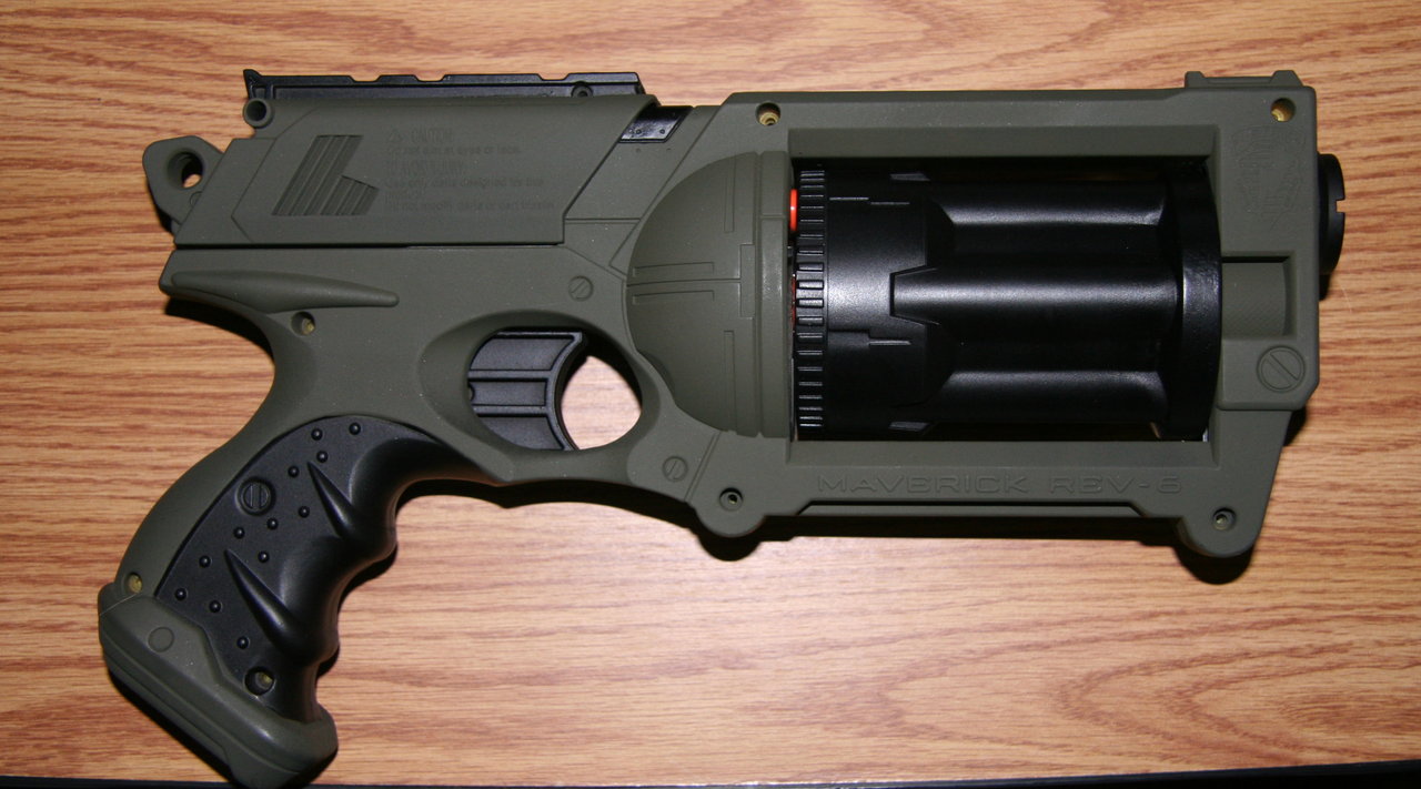
3.) Army green & black style:
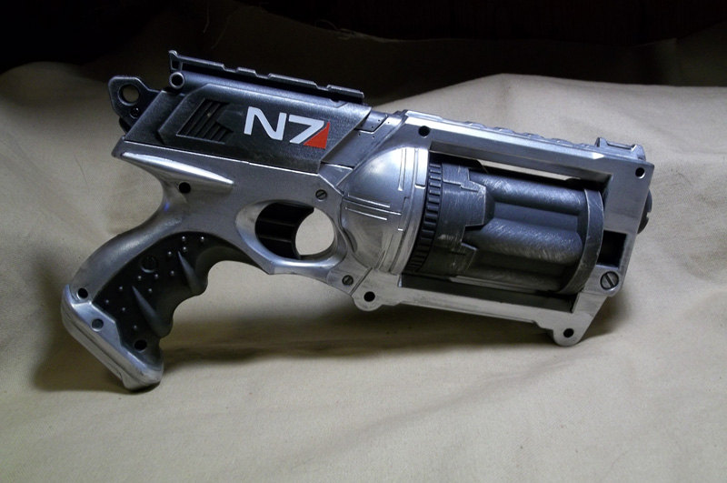
4.) silver & black (mas effect I think? not a gamer).. really like this style too.. even the logo (of some kind) looks right
5.) mixture, black, silver & brown grip..
Secondly.. a few other questions.. ![]()
1.) how important (cool points?) is that the nerf gun still works as a nerf gun? Ive been thinking of removing the working 'dart' aspect of it.. in favor of some electronics goodness instead?? thoughts?
2.) anyone else have a blaster project in the works??
-----------------------------[update after some work]--------------------------------
update.....
after some work.. I made some progress on this project. ![]()
I got the electronics all figured out.. (including making/baking/assembling the board, writing/finalizing the code, home brew/etching two additional custom pcb's...yadda yadda)
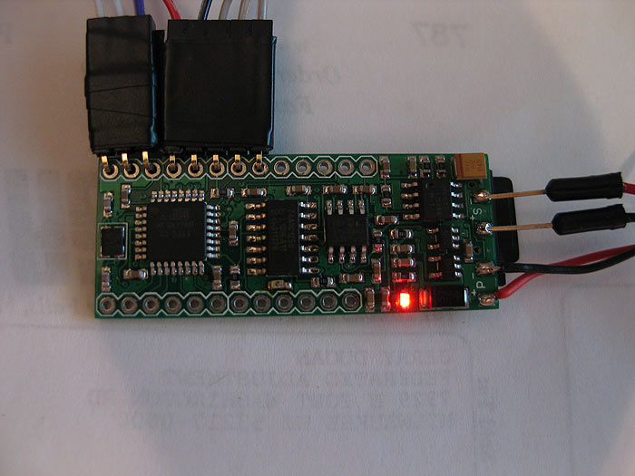
It is powered by S.C.A.B... ![]()
[kinda my generic/general platform for props..so far I love it]
I think I had posted pics of making my board somewhere before.. (in another thread currently running about)..
here it was it looks like:
here it is on the left next to an Arduino board (with a WaveShield stacked on top of it for comparison)
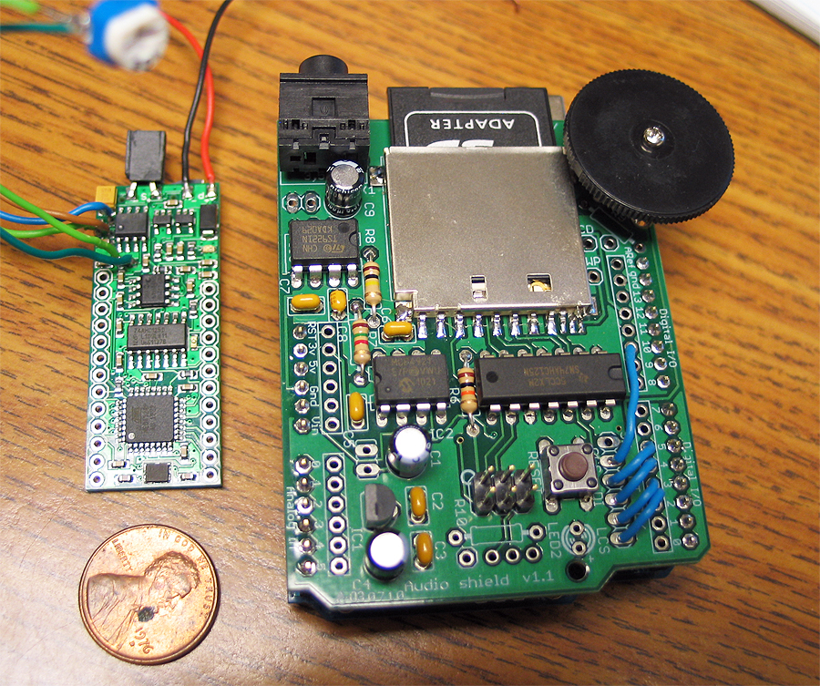
(fonts changeable on SD card, reads/loads a few defaults off a text file on SD card as well to set a few parameters on the blaster)
*safety = if on.. you need to have the trigger pressed when you boot up
*maxammo = total ammo count before having to reload
*acolor = led color when in auto-fire mode (can be r, b, or g)
*acolor = led color when in semi/manual fire mode (can be r, b, or g)
here is the first video of stage/phase one of the electronics and code development stage of it:
Prepping the nerf gun: (in no particular order)
*I needed a motor.. but didnt really know how I was gonna make it all work.. about torque on motors...sizes..etc..
got lucky and scored a motor that looked like it would fit from my local science surplus store.. biggest I could find that was small enough to still fit..lol (it seemed like it was MADE for the gun once I got it home)
*I knew I need to somehow get some leds into the barrel.. and wanted to have it be RGB..
*Wanted it to reload by pulling the slide on top back
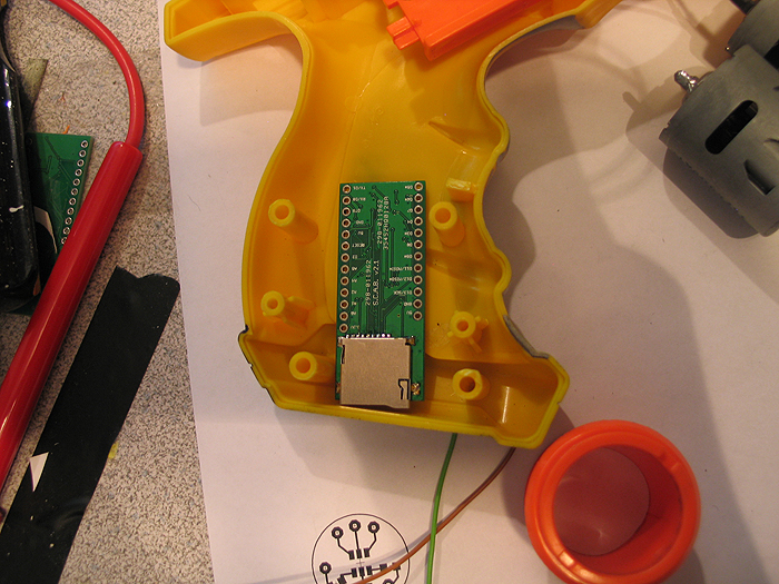
*Since its a blaster the SD card and batteries needed to be accessible without having to open the the gun up (ie: accessible sd card and re-charge port)
*Needed to account for a switch/button to switch from semi/manual firing mode to auto-firing mode
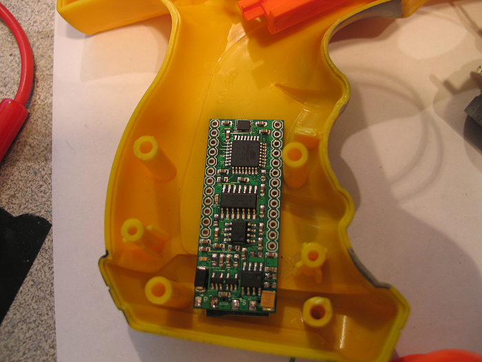
here was my first mock up for testing space and how I was gonna attempt things: (pre dynamic default loading)
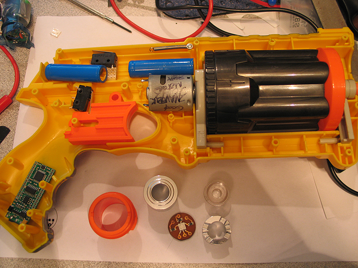
(s.c.a.b. in grip/butt)
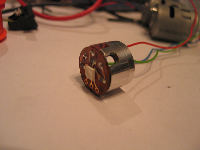
motor:
after taking apart the Maverick gun (many tutorials all over on it if needed).. I saw how the barrel was turned internally by trigger pull.. and figured Id hack/modify it to suit my needs.
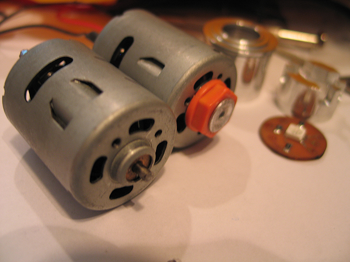
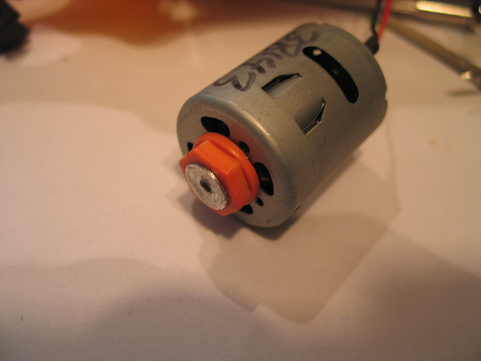
I cut/sanded the hexed shaped top off the post/part that connected to the barrel and turned a little inner sleeve and press fit hole so it would attach to the cut down motor shaft.
before/after motors:
** what you dont see pictured is any pics of the custom PCB I etched for the components to drive the motor (SCAB/Arduino do not have enough power itself to drive high power devices.. so you need a driver/transistor...etc.. something to help out)
but here are the shcematic and pcb files I made in eagle for it:
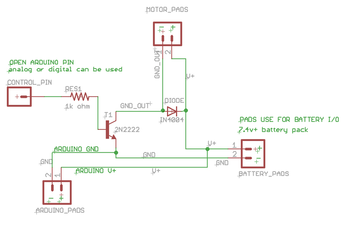
[img width=568 height=768]http://dmstudios.net/misc/motor_pcb/motor_pcb_2.jpg" />
RGB barrel LED:
I was going to use a DX RGB led star I had laying around.. but then decided it was over kill for a blaster (not like I need to light up a poly tube/blade or anything)..
so I opted for a 505 RGB led,.
*created a custom home etched pcb for it
*turned down a two piece optics holder and pcb 'presser up againster' unit to hold everything.. (similar to Ace's small OD optics/holders... but mine are much more shitty and crude..and no threading....well you get the point).. haha..
I wont go into detail on how I etched.. I have posted a few tutorials stp-by-step on how to make these at home in 10 minutes enough..
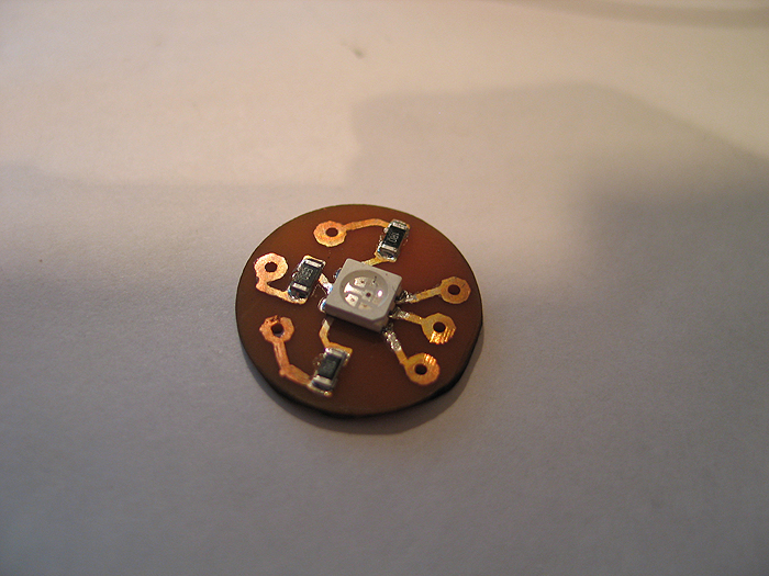
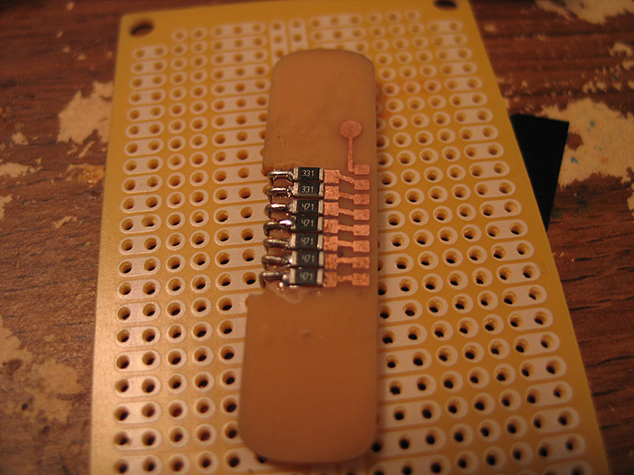
after etching.. smear some solder paste.. and populate board with resistors & 505 RGB:
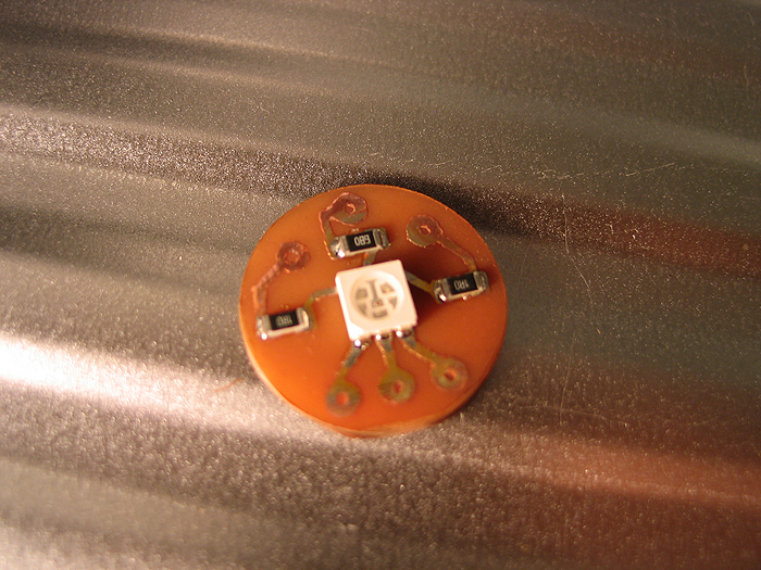
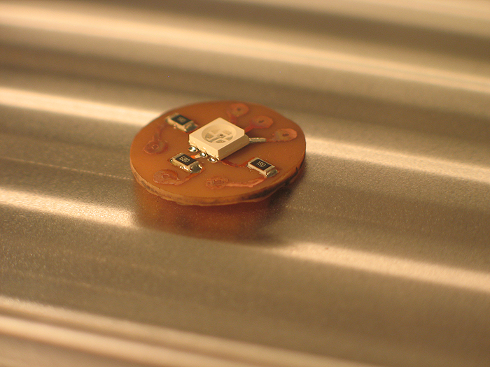
bake it in toaster oven:
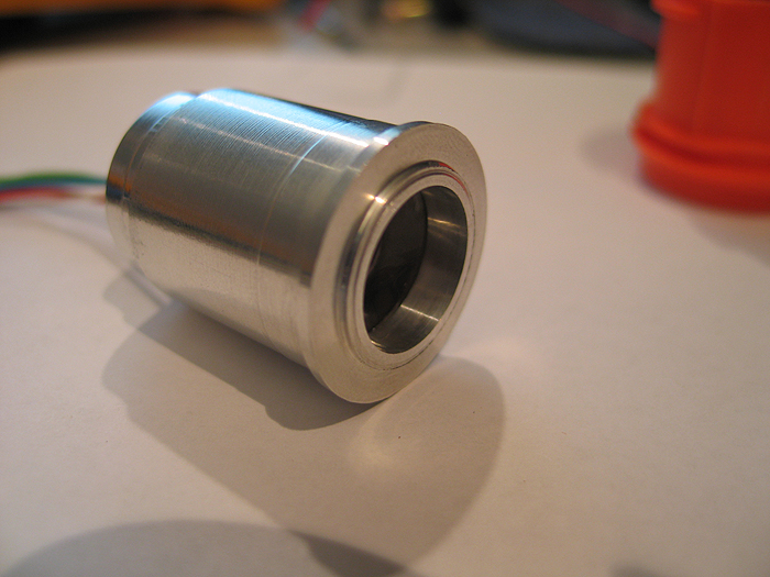
make inner sleeve/bottom portion to hold/push the pcb with (incuding some milled out section for wire passing)
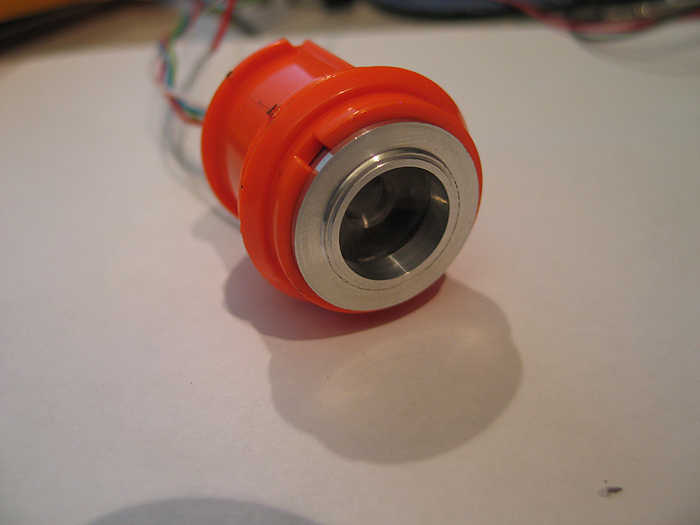
make outter sleeve to hold optics in it.. and also has the bottom portion slide in and sandwhich the pcb up against the optics......and fits in the Maverick gun plastic barrel part:
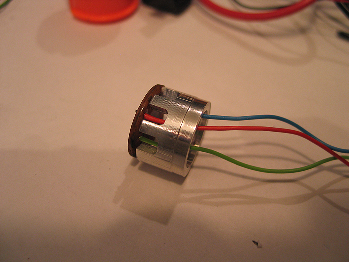
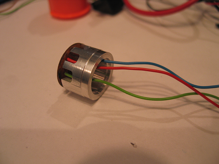
Unit all put together:
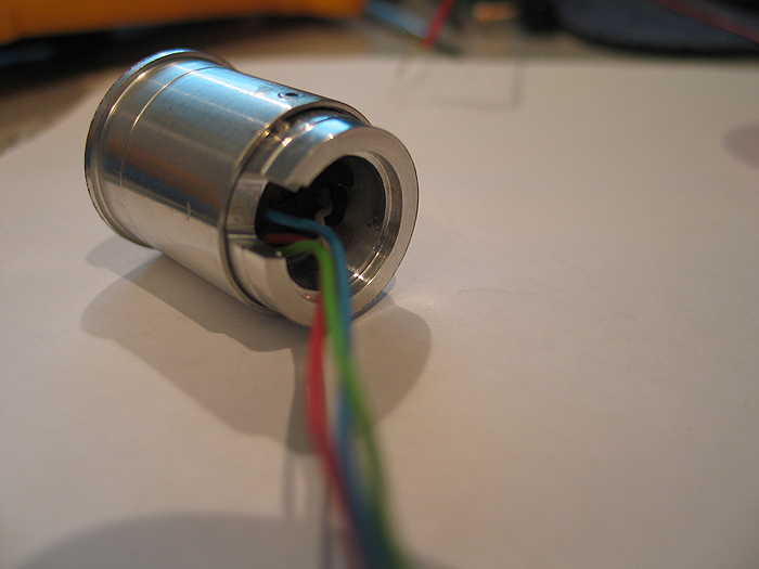
Inside the Maverick barrel:
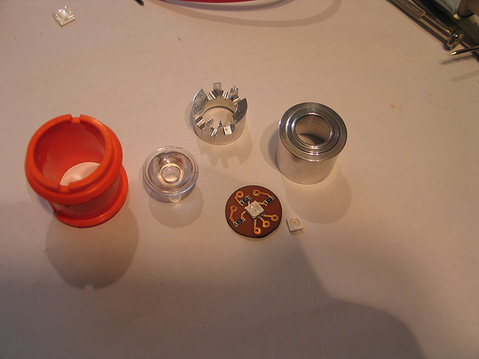
Exploded view of all parts/optics/pcb..etc:
Switches:
Mode select switch.. had to think about where I was gonna put this.. without some huge, ugly slider switch somewhere.. that looked like an after-thought...
I eventually decided to re-purpose the same button/area that used to allow the barrel to swing out and reload the darts..
*(this switch has an led in it.. I am nto currently using it.. but could be used to have the switch backlit.. I have a 3.3v pad on the board)
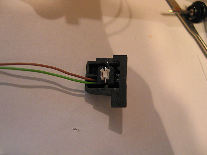
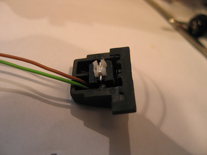
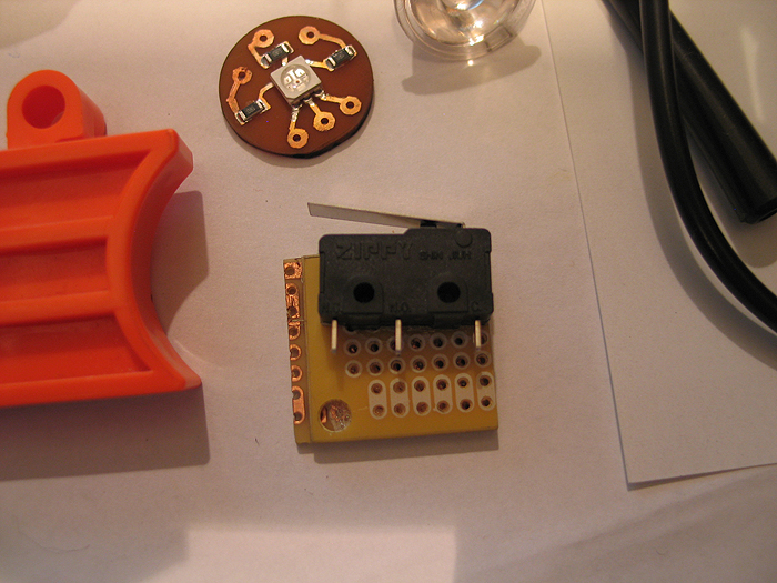
using a simple lever switch.. for both both main trigger and reload..
reload switch:
this one is secured to some perfboard cut to snug fit for inside the gun area.. it positions it in the correct place so the top slide hits it when pulled back, w/o mod to the top slide area/parts
main trigger:
you can see where I placed it int he above overview shot of the gun layout..
I mod'd/filed down the trigger a bit to hold the lever from the switch it in easier...(works great!)
after getting all this work and aligning things up.. I did a quick mock-up and cram-fu test with it mostly assembled.. (some parts have to wait for final paint and/or assembly)..
I took this video of its current state.. which Im calling 'done'.. and ready for break down and final paint & weathering (attempts) lol
thanks for the poll/feedback..
Im still not sure about trying a chrome/silver/nickle base and some dark washes.. or going with a black base..and trying to silver/grey dry brushing..etc.
(better decide soon eh?) lol
:005:
MHS [modified] control box (my entry in cram-fu)
been playing around with a few ideas over the years.. and have worked on a few control box ideas/projects as well...
this one is based off an MHS control box.. with some 'modifications' ![]()
things to note:
*has two switches (main and aux) in it.. (one the 'side' of the box.. with custom switches and switch caps/stems
*custom PCB was created for them to mounted, to and mounted to the inside of the box.
*has a 1.3mm recharge port in it
* has custom smd led bar graph (custom made pcb for this as well)
pretty has everything a hilt needs, all located in the......... 'control box' ![]()
posting my mock up pics... if things work out good.. (which it look sot be great even).. I'll break it down again.. re-fine...and buff/polish and powder coat for the finished product.
hopefully this gives some ideas for everyone else... make things work for you!.. make what you need...
lets begin:
1.) take your favorite drawing app and make a PCB design.. no special tools.. draw BLACK lines/traces and pads where you want 'copper' to be..
get your copper clad board/section..
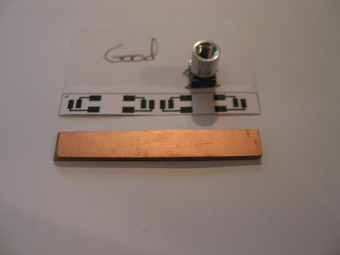
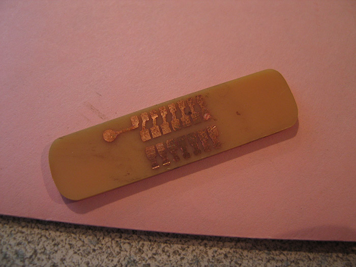
2.) print out image on glossy photo paper.... iron/transfer image/toner to the copper board.. rinse under water to remove paper.. soak in etchant to remove exposed copper:
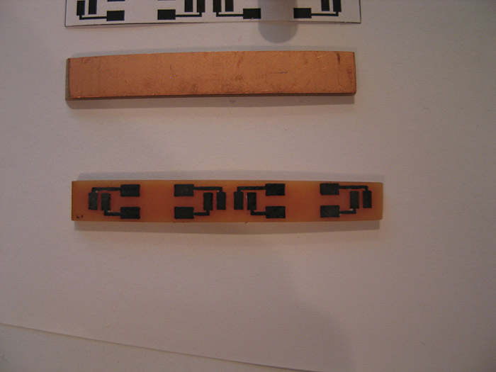
3.) after exposed copper is gone.... use a q-tip and some mail polish remover to remove the toner from the pcb... (revealing the copper/pcb under neath)
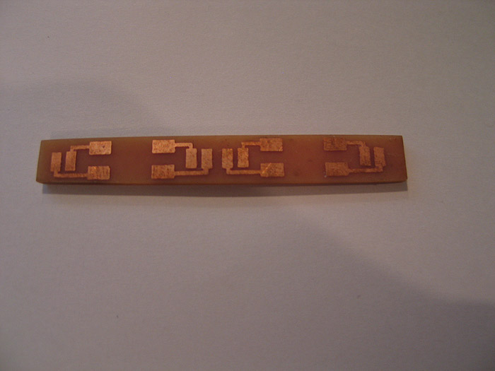
***(all this above has been posted many times before.. and shame on you for not trying it!... this could have saved your ass in that 'one' project!) =)
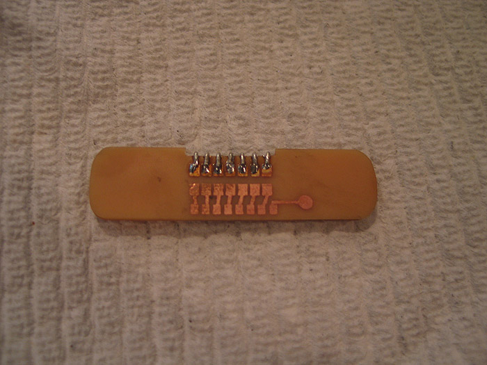
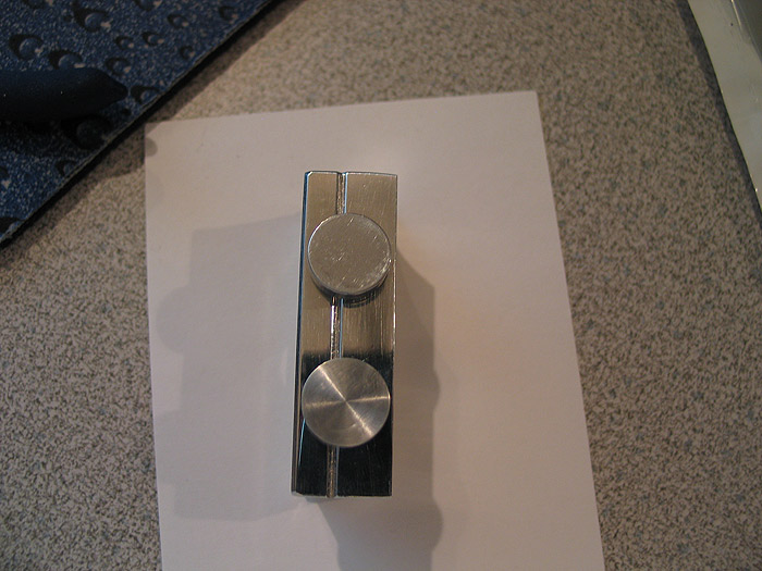
4.) mounted my modified switches to their PCB.. (these have the threaded tops on them for external switch caps to be used form outside the hilt.. keeping the main core/chassis/box internals standalone)
several solder pads depending on the need/space available
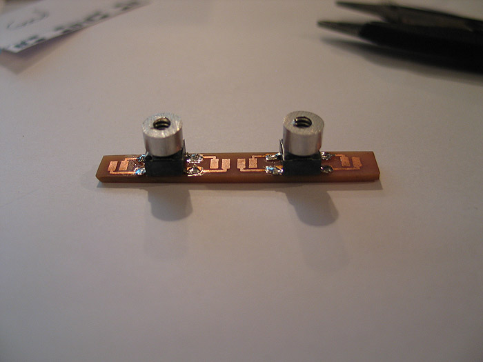
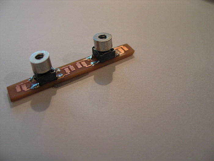
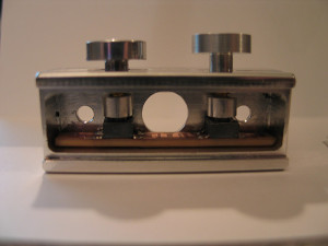
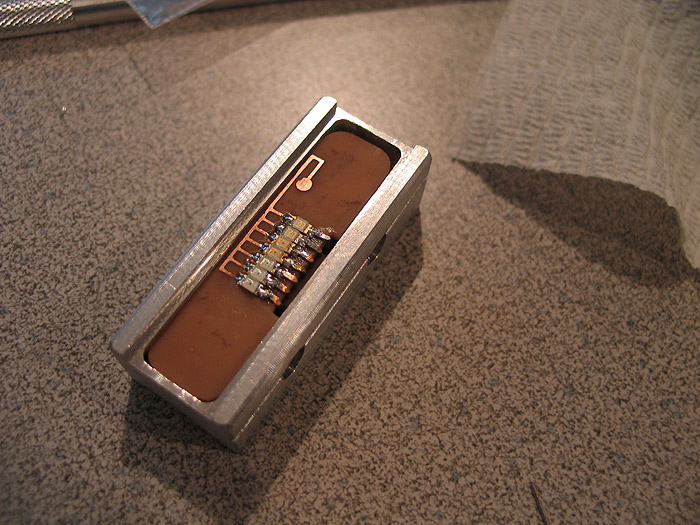
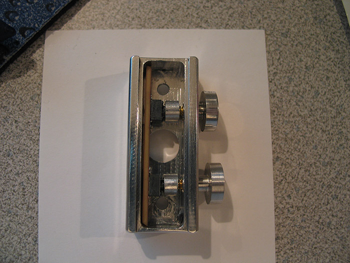
5.) mounted (mocked up) in the control box:
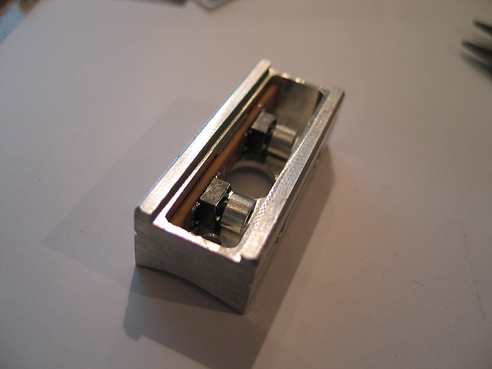
6.) (although it looks 'off' its really just the pic.. things line up great!)
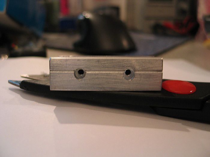
side view of holes and where the switch tops are
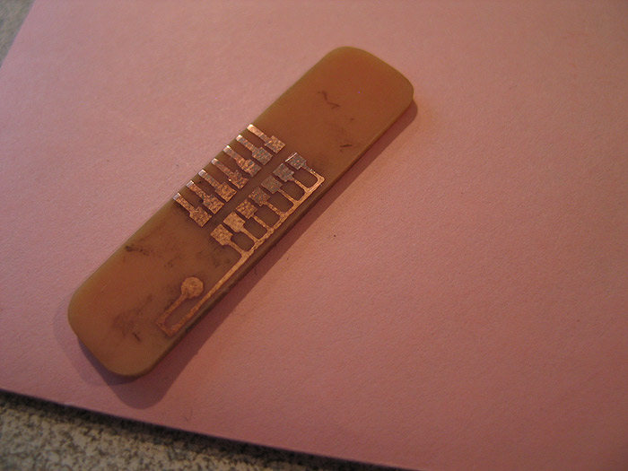
7.) top (custom) pcb made..for the led bar graph.. (this posed a problem due to space.. and the fact that I wanted each led to be addressable for either all direct drive..'or' for CF led.txt sequence..etc.. not to mention trying to do double sided board without through hole plating.. (making my own)..
again.. space was concern.. (both sides)
I think an led (possible two) got ruined by heat? or something.. but Im going to replace them real quick. (as they only light up partially)
in the end it will be black box.. aluminum top plate and aluminum switches on the side of the box.
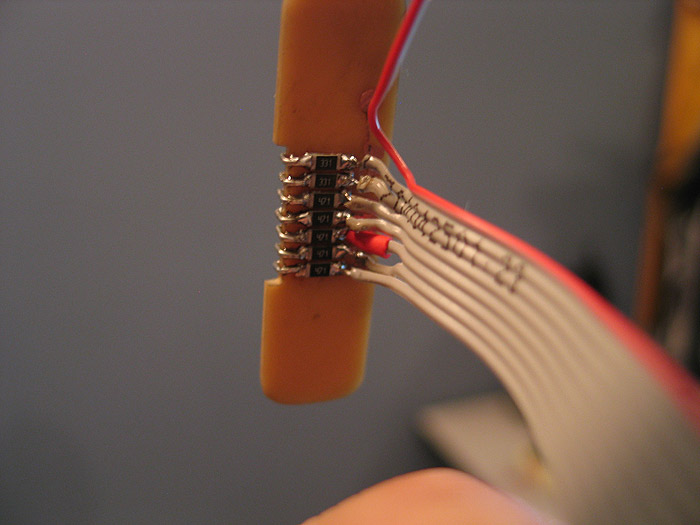
the top 'smd led bra graph' pcb/portion
this is where each resistors goes: (bottom of board)
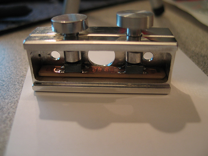
quick mock up:
(again the switch pcb is in place already.. the custom pcb's are almost forming a box to support each other
---------------------------------------------------------------------------------------------------
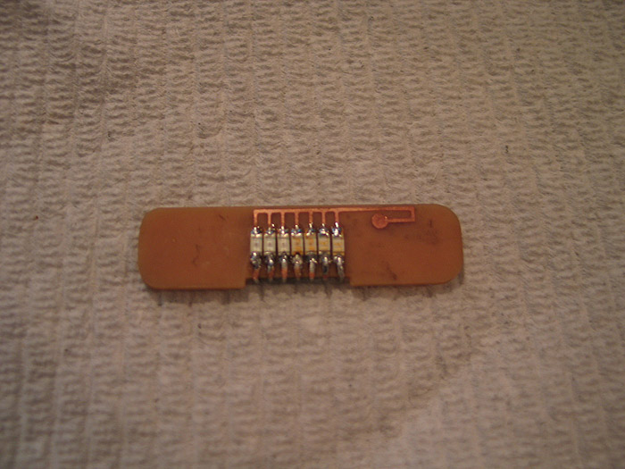
got a couple hours the other night to finish 95% of it up... (I think 'real' professional PCB's would serve best here)
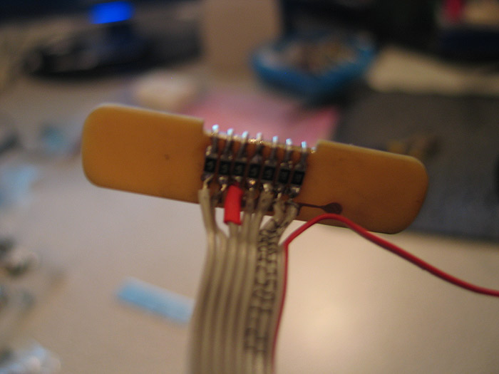
got the bottom half of the bar graph competed (resistors soldered, wires soldered..etc)
used 1206 resistors.. all I had at the time.. (yesterday my 0603's came.. had I had those in my plannign stage..I think everything might have been topside mounted....oh well v2 I guess..lol..this is my PoC)
still not quite sure how/where to tap the V++ to.. I have a few ideas...not a big deal though any place will work) ![]()
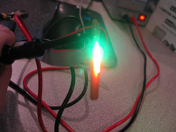
quick test of being lit up.. (had to replace 2 leds as I think they were 'damaged' by initial placement? maybe soldering too hot? different bin? one was of color.. when lit up bright..then gradually died out after a few seconds)..anyways replaced them
2 x green
2 x yellow
3 x red
each resistored, each individually addressable... (so can be direct driven, used with CF, or as PLI) =)
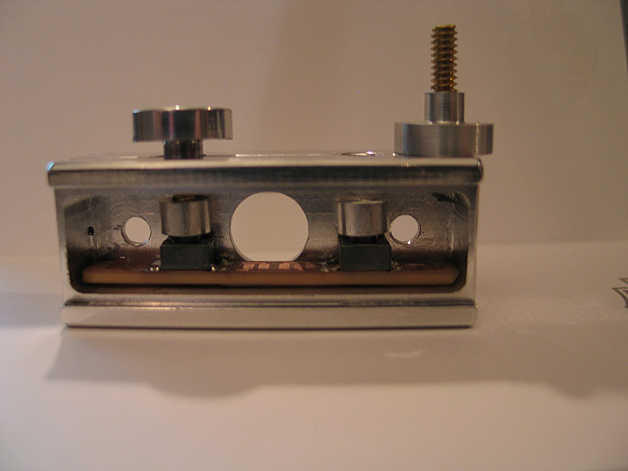
quick mock up of the side/switch PCB inside the box. and the switches/caps/stems I made for them.. (still need to be shortened a bit..but they are close enough to work and show the effect/style)
more pics of the 'switch caps/stems'

the pcb's took about 30 minutes total to make.. (probably another 15 prior on trial and error on printing out paper copies and doing size checks)
now that I feel the idea is 'sound' I'll go back and plan it out a bit better.. (this is supposed to still have recharge port added..but Im not sure after implementing things this far it will make the cut)
time to break it down.. pc the control box BLACK..
buff/polish the 'switches'...
and complete the 'top'.. which is an already sized aluminum strip that sits flush like any normal 'card stock'
there is NOW window cut/milled out of it yet through for the bar graph.. =(
enjoy.