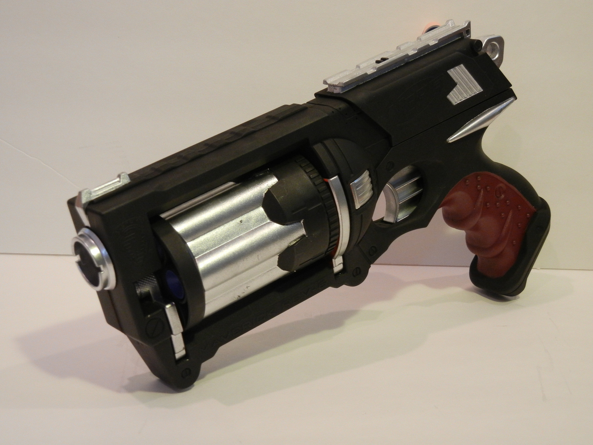
Maverick (Nerf) Mod: custom blaster build log

Looking to do a Nerf gun mod... wanted to get some feedback on how to paint/weather it..
found a few projects on-line that I thought we pretty decent.. trying to decide on my own direction here.
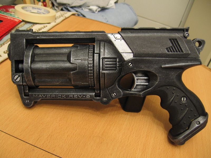
1.) black & silver based (techy) theme
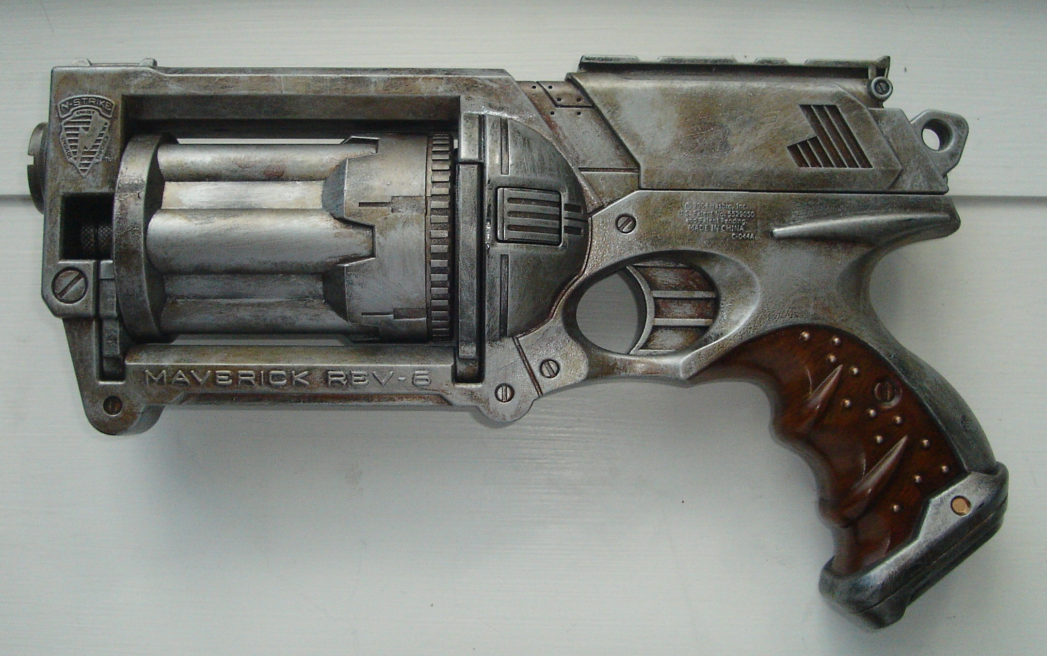
2.) heavy metal/blade runner feel (really digging this one and the wooden/brown handle on it)
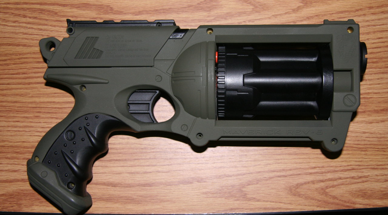
3.) Army green & black style:
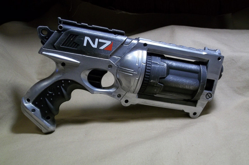
4.) silver & black (mas effect I think? not a gamer).. really like this style too.. even the logo (of some kind) looks right
5.) mixture, black, silver & brown grip..
Secondly.. a few other questions.. ![]()
1.) how important (cool points?) is that the nerf gun still works as a nerf gun? Ive been thinking of removing the working 'dart' aspect of it.. in favor of some electronics goodness instead?? thoughts?
2.) anyone else have a blaster project in the works??
-----------------------------[update after some work]--------------------------------
update.....
after some work.. I made some progress on this project. ![]()
I got the electronics all figured out.. (including making/baking/assembling the board, writing/finalizing the code, home brew/etching two additional custom pcb's...yadda yadda)
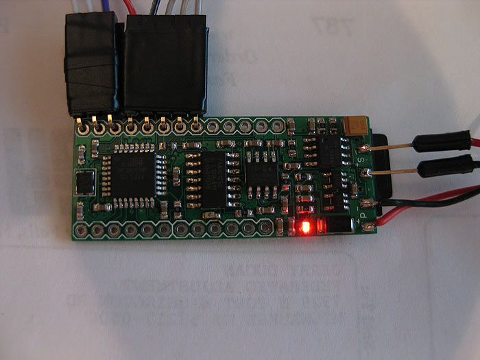
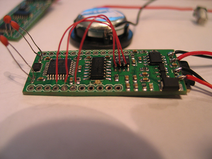
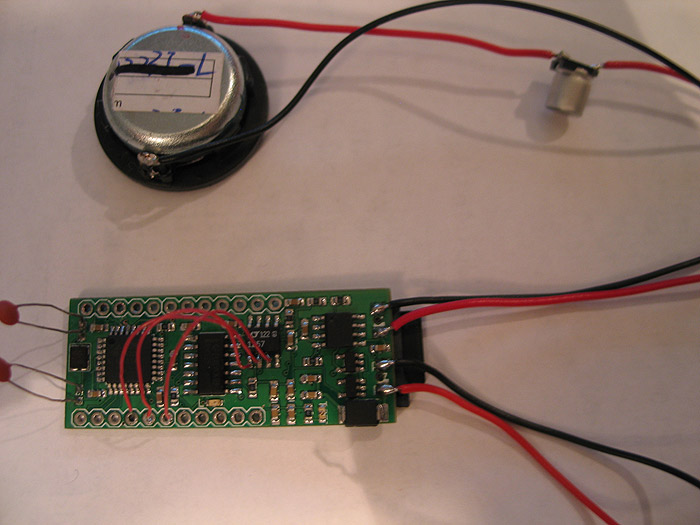
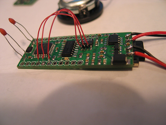
It is powered by S.C.A.B... ![]()
[kinda my generic/general platform for props..so far I love it]
I think I had posted pics of making my board somewhere before.. (in another thread currently running about)..
here it was it looks like:
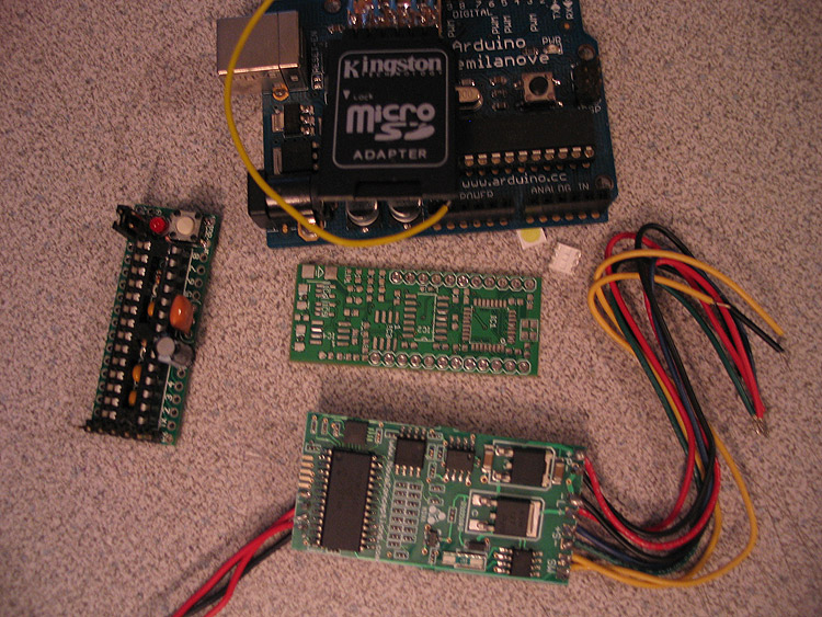
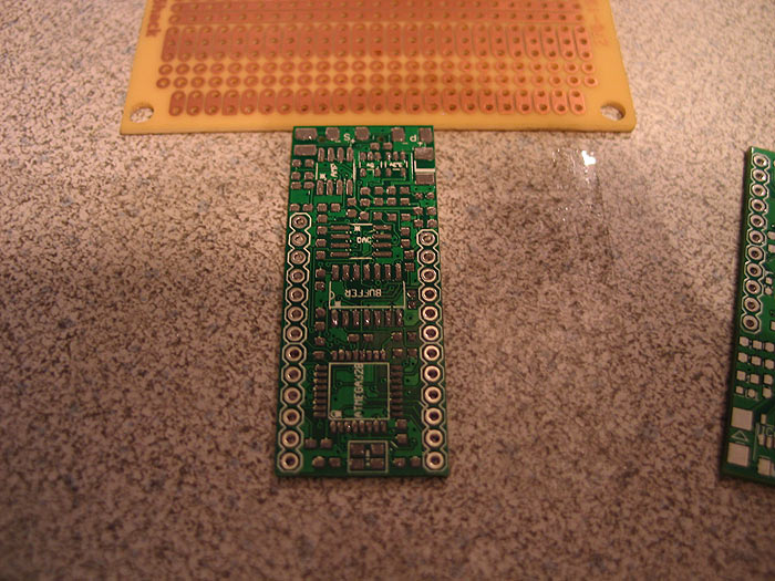
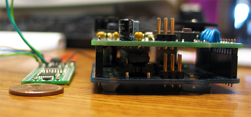
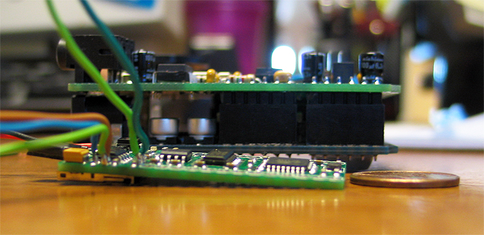
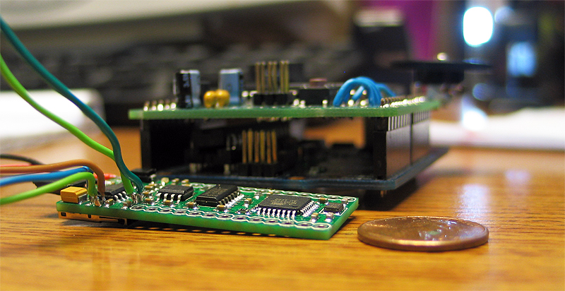
here it is on the left next to an Arduino board (with a WaveShield stacked on top of it for comparison)
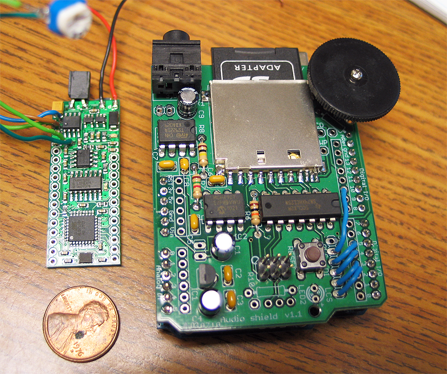
(fonts changeable on SD card, reads/loads a few defaults off a text file on SD card as well to set a few parameters on the blaster)
*safety = if on.. you need to have the trigger pressed when you boot up
*maxammo = total ammo count before having to reload
*acolor = led color when in auto-fire mode (can be r, b, or g)
*acolor = led color when in semi/manual fire mode (can be r, b, or g)
here is the first video of stage/phase one of the electronics and code development stage of it:
Prepping the nerf gun: (in no particular order)
*I needed a motor.. but didnt really know how I was gonna make it all work.. about torque on motors...sizes..etc..
got lucky and scored a motor that looked like it would fit from my local science surplus store.. biggest I could find that was small enough to still fit..lol (it seemed like it was MADE for the gun once I got it home)
*I knew I need to somehow get some leds into the barrel.. and wanted to have it be RGB..
*Wanted it to reload by pulling the slide on top back
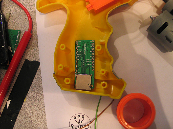
*Since its a blaster the SD card and batteries needed to be accessible without having to open the the gun up (ie: accessible sd card and re-charge port)
*Needed to account for a switch/button to switch from semi/manual firing mode to auto-firing mode
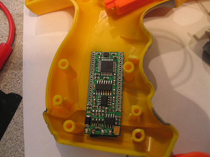
here was my first mock up for testing space and how I was gonna attempt things: (pre dynamic default loading)
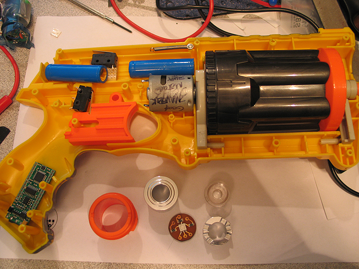
(s.c.a.b. in grip/butt)
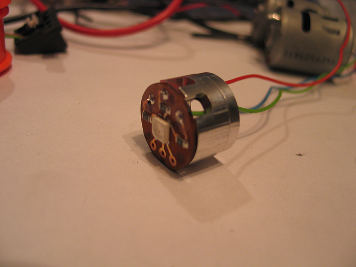
motor:
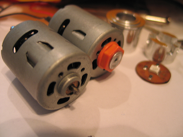
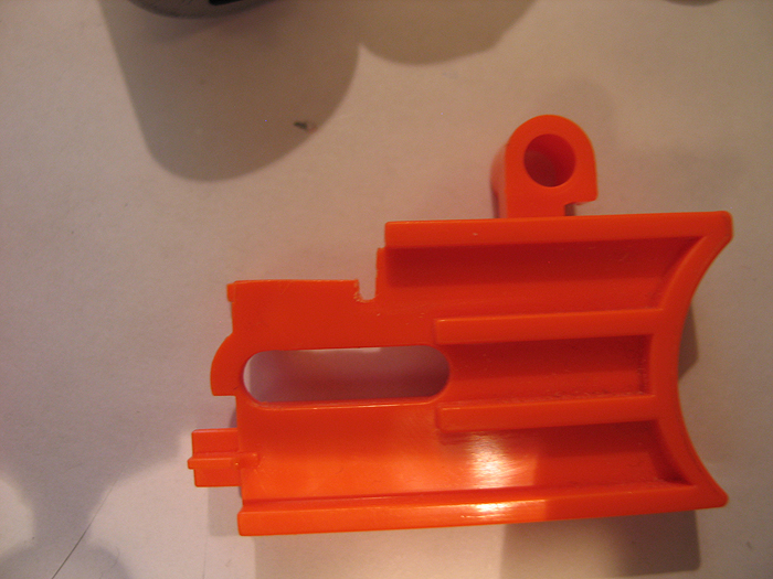
after taking apart the Maverick gun (many tutorials all over on it if needed).. I saw how the barrel was turned internally by trigger pull.. and figured Id hack/modify it to suit my needs.
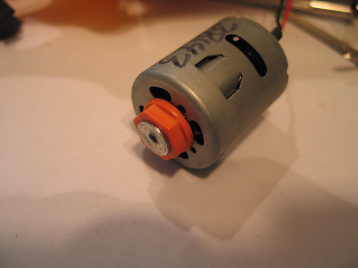
I cut/sanded the hexed shaped top off the post/part that connected to the barrel and turned a little inner sleeve and press fit hole so it would attach to the cut down motor shaft.
before/after motors:
** what you dont see pictured is any pics of the custom PCB I etched for the components to drive the motor (SCAB/Arduino do not have enough power itself to drive high power devices.. so you need a driver/transistor...etc.. something to help out)
but here are the shcematic and pcb files I made in eagle for it:
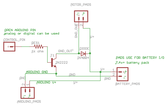
[img width=568 height=768]http://dmstudios.net/misc/motor_pcb/motor_pcb_2.jpg" />
RGB barrel LED:
I was going to use a DX RGB led star I had laying around.. but then decided it was over kill for a blaster (not like I need to light up a poly tube/blade or anything)..
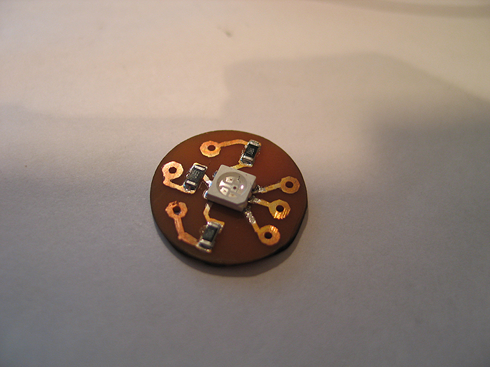
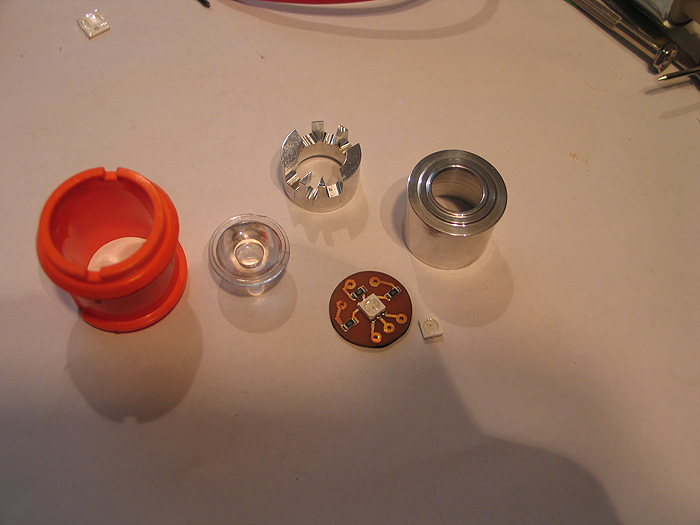
so I opted for a 505 RGB led,.
*created a custom home etched pcb for it
*turned down a two piece optics holder and pcb 'presser up againster' unit to hold everything.. (similar to Ace's small OD optics/holders... but mine are much more shitty and crude..and no threading....well you get the point).. haha..
I wont go into detail on how I etched.. I have posted a few tutorials stp-by-step on how to make these at home in 10 minutes enough..
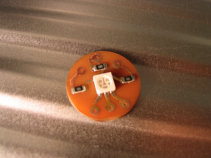
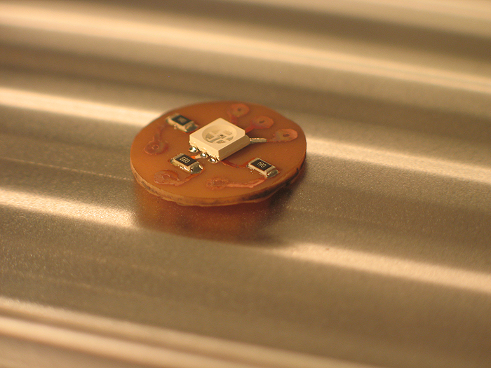
after etching.. smear some solder paste.. and populate board with resistors & 505 RGB:
bake it in toaster oven:
make inner sleeve/bottom portion to hold/push the pcb with (incuding some milled out section for wire passing)
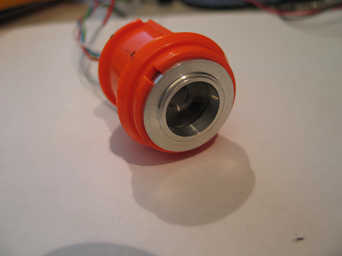
make outter sleeve to hold optics in it.. and also has the bottom portion slide in and sandwhich the pcb up against the optics......and fits in the Maverick gun plastic barrel part:
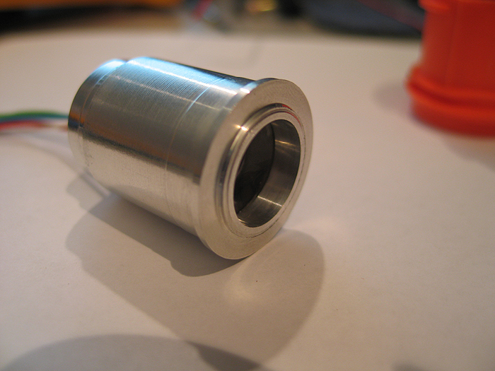
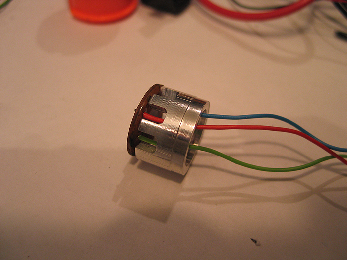
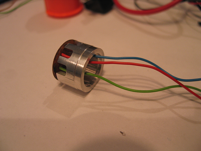
Unit all put together:
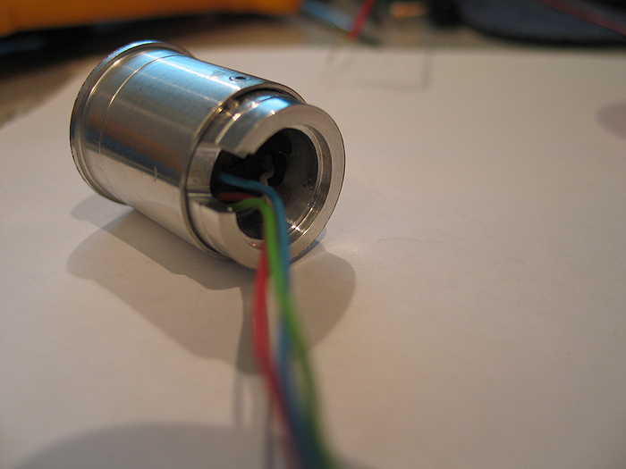
Inside the Maverick barrel:
Exploded view of all parts/optics/pcb..etc:
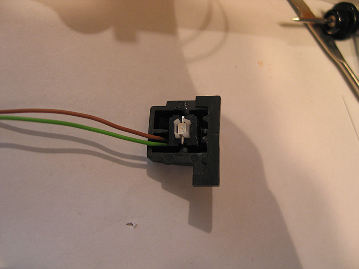
Switches:
Mode select switch.. had to think about where I was gonna put this.. without some huge, ugly slider switch somewhere.. that looked like an after-thought...
I eventually decided to re-purpose the same button/area that used to allow the barrel to swing out and reload the darts..
*(this switch has an led in it.. I am nto currently using it.. but could be used to have the switch backlit.. I have a 3.3v pad on the board)
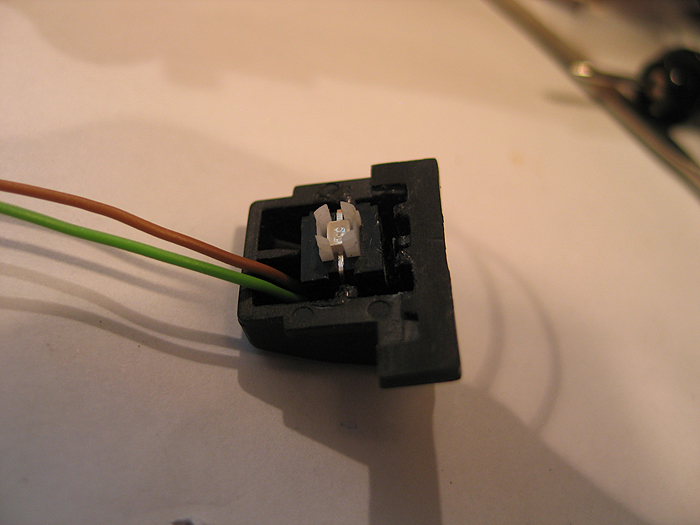
using a simple lever switch.. for both both main trigger and reload..
reload switch:
this one is secured to some perfboard cut to snug fit for inside the gun area.. it positions it in the correct place so the top slide hits it when pulled back, w/o mod to the top slide area/parts
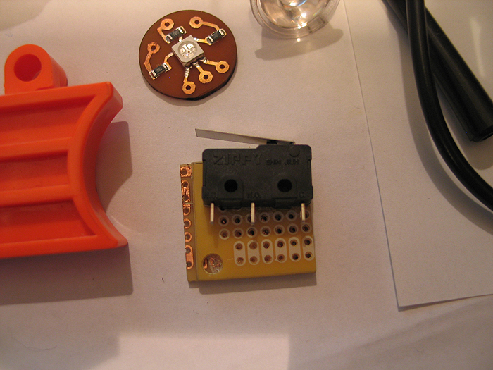
main trigger:
you can see where I placed it int he above overview shot of the gun layout..
I mod'd/filed down the trigger a bit to hold the lever from the switch it in easier...(works great!)
after getting all this work and aligning things up.. I did a quick mock-up and cram-fu test with it mostly assembled.. (some parts have to wait for final paint and/or assembly)..
I took this video of its current state.. which Im calling 'done'.. and ready for break down and final paint & weathering (attempts) lol
thanks for the poll/feedback..
Im still not sure about trying a chrome/silver/nickle base and some dark washes.. or going with a black base..and trying to silver/grey dry brushing..etc.
(better decide soon eh?) lol
:005:
S.C.A.B development…

Over the 'years'.. (since I was first turned on to the RFX project/platform).. I fell in love with the idea of a generic platform for the user use as they saw fit.
motors, leds, rfid...whatever the project was.. a nice, simple, generic platform for users to 'tweak' and customize seems like a great idea to me.
with RFX basically defunct/dead... I turned toward the Arduino platform. Had a huge following, lots of examples.. and quite easy to get up to speed on basics..etc.. (even without an electronics background)
The problem with the Arduino platform (as is).. is that its purpose (to me) is for developing/prototyping your projects.. but not to be used in the end application.
why? due to size.. and price mainly for me.. (although other Arduino variants can come in smaller sizes.. the price is includes extra development stuff you may not use in your final projects...etc... and not to mention a minimal Arduino circuit can be made for under $7.00 bucks!)
And getting an Arduino to play audio isnt done easily (by default)..
****(although now I just tested a super easy PWM based audio output library.. doesnt use any DAC or AMP.. and the quality is pretty decent for what it is!)
SO I began to teach myself Eagle.. (not easy for me unfortunately..but after some time I got more comfortable with it)..
and laid out some stuff.. and finally felt confident enough to start making my own PCB's and having the shipped to me.. (instead of the old DIY home brew etch approach)
So here I am documenting my process.. (and failures) along the way.. ![]()
a qcuik summary of the things I had to learn.do/involved..
*need to make a the schematic/circuit layout in Eagle
*hope its correct or have others look it over (check against design rules too)
*order the pcb's (sending the exported GERBER files form Eagle to your pcb fab house of choice)
*order a stencil (which is used to layover the pcb and smear solder paste over it to get it applied to the exposed pads through stencil)
*place parts on pcb (tweezers!!!!)
*re-flow pcb in oven
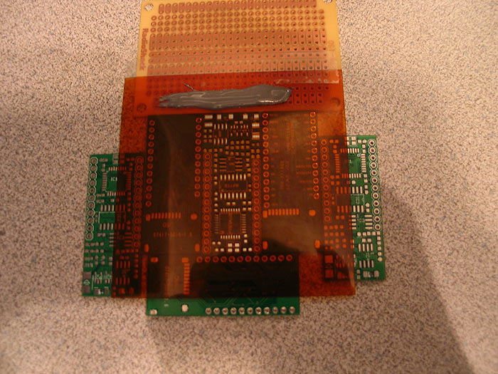
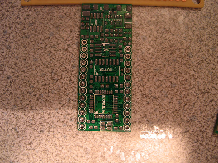
This was my first iteration.. using a different DAC than the schematic I was using as my guide:
Here was my FIRST generation of pcb's I got made:
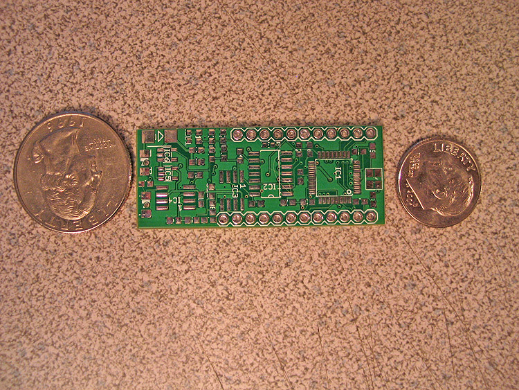
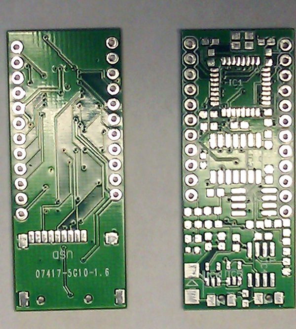
Here is the pcb compared to other stuff.. an Arduino, a smaller minimal Arduino kit..and I think an US 2.5 board:
here I applied my solder paste.. and populated the board with its components..etc. and re-flowed in my wal-mart toaster oven!!
re-flowed:(done)
I had even tried to fix it by testing jumper wires to the default I/O pins..etc.. (no go)..
Well long story short.. after posting and asking....I just couldnt get it working with the DAC I had chosen..maybe someone else could have?? no clue.. (DOH.. should have just followed along..lesson learned)..which I guess is good.. as I had a few other mistakes as well.. =( SO I started over.
In the end, all I had was a tiny Arduino circuit..with on-board uSD socket.. nice.. but no audio output. ![]()
So lets go version 2!!
I got mew pcb's made... got a new stencil made..etc.. and started again.
Here is the process "I" did:
apply the solder paste, using stencil:
remove stencil.. examine paste placement on pads: doesnt need to be PERFECT as the heat from pads will pull solder towards it..etc:
Then populate board: (those TQFP chips are a PITA sometimes!!)
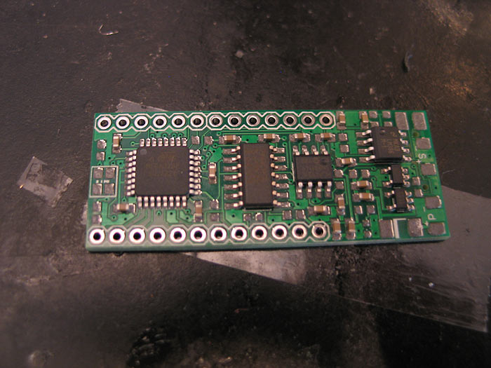
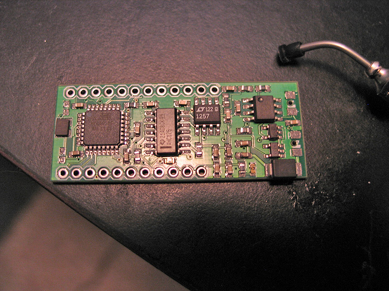
Stick it in the toaster for a bit.. (you can see the solder melt and get shiny)
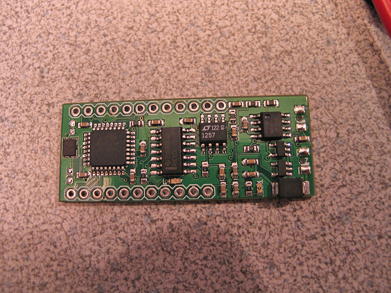
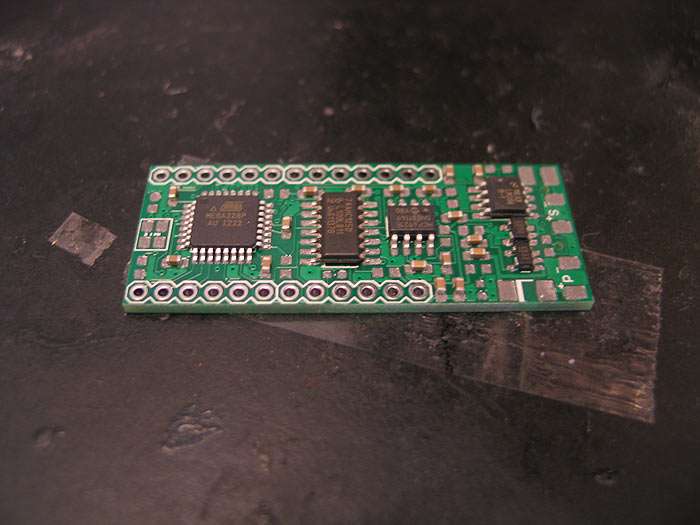
and when you are done you get a finished board..
Here are some size shots and comparison shots against a full size Arduino & WaveShield (which is what my custom board is together..those two boards in one)


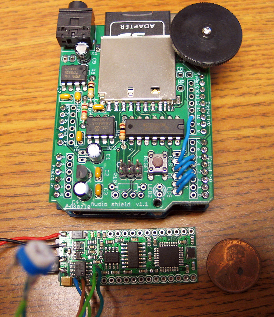
in the last pic you can see some pots wired inplace of some resistors.. I did this so I could dial in not only the volume.. but play with the filter/range, so things didnt sound so muddy/muted..
when done flash the board with whatever code you wrote to control/do whatever it is you need done.
thanks for looking.. was a fun project..
Arduino: WaveShiled build process
Hey gang-
while I was working on my own custom Arduino based project.. I found myself without a real way to compare the audio output (volume/quality) against the Adafruit WaveShield which I based my project off of)
So I was about to order one.. when I found a guy at my local makerspace that actually had one of these kits. The catch was he had never put it together.
So the barter was on.. I can borrow and test it.. as long as I put it together for him.. (pfft.. no problem!)
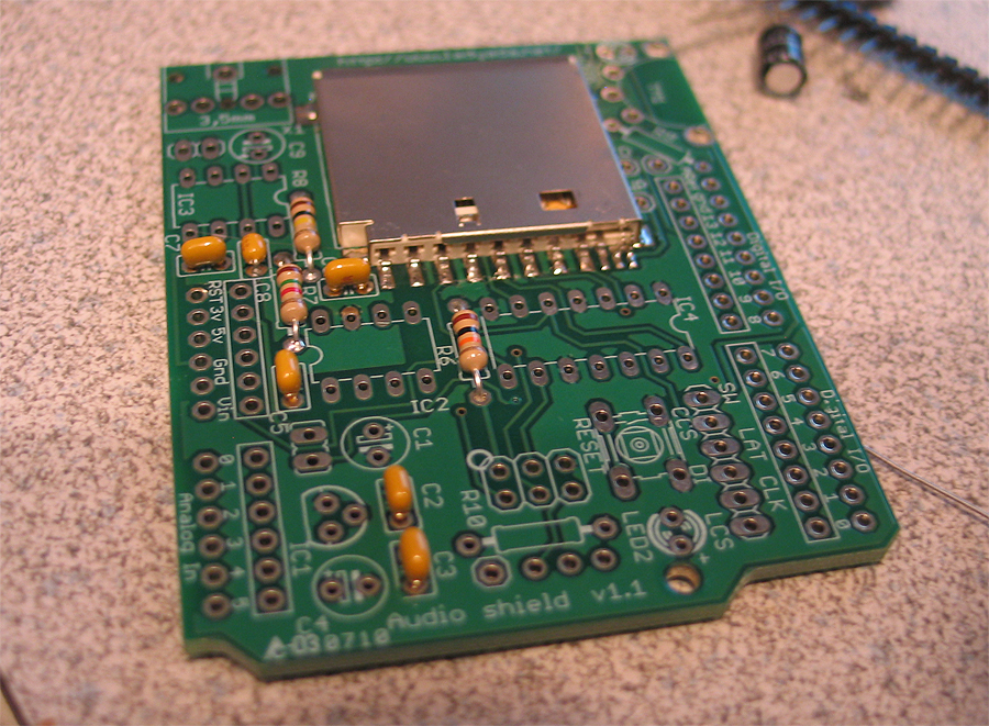
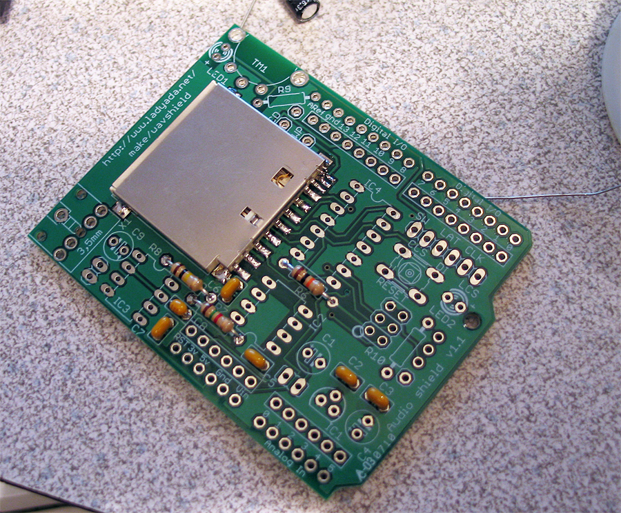
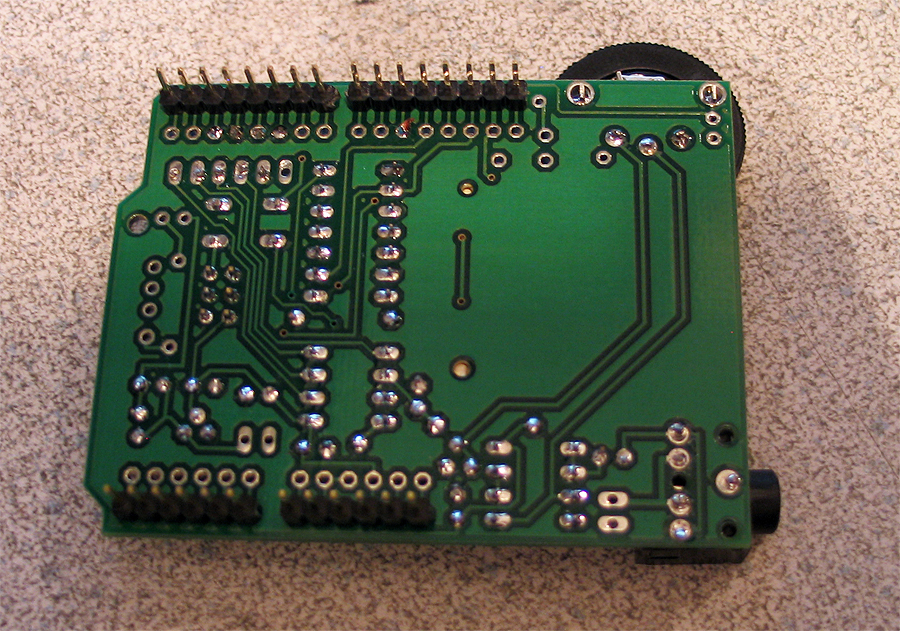
Here is my documentation of building an Adafruit WaveShield..
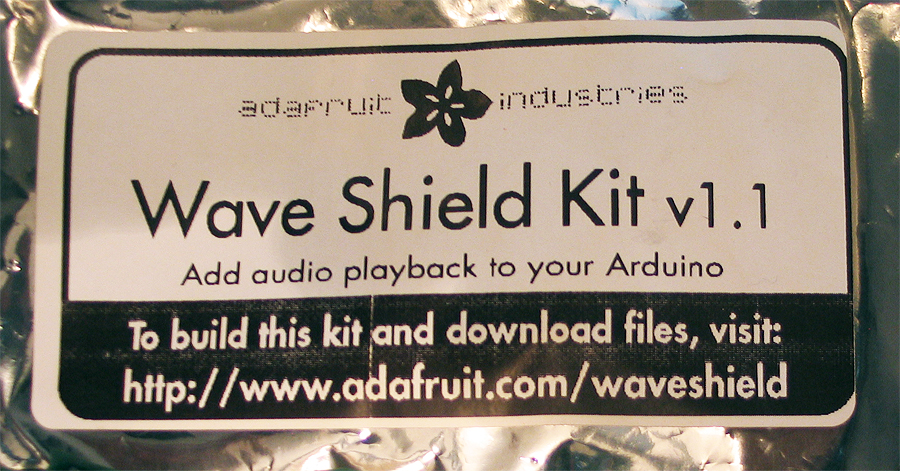
the kit parts:
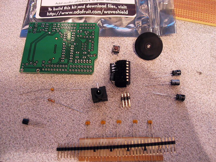
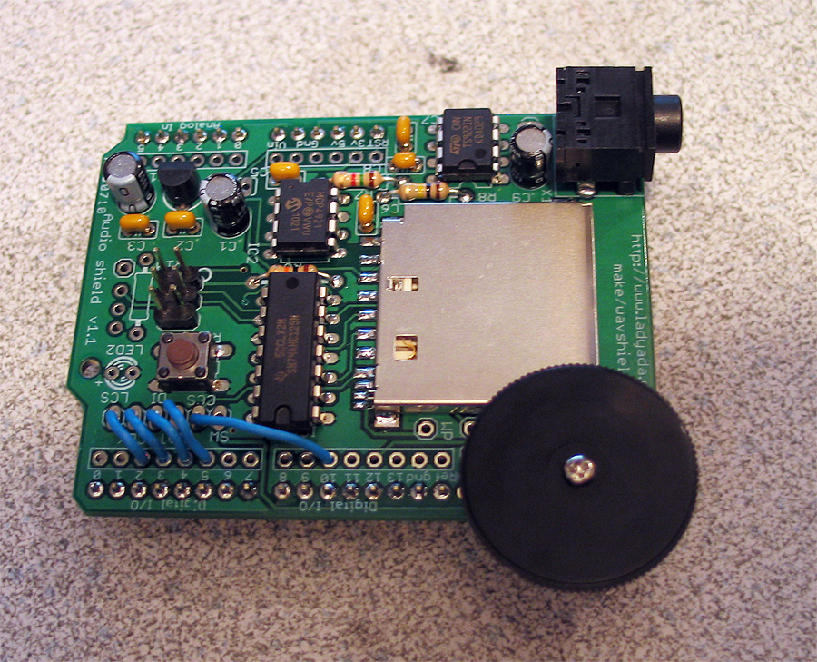
compare shots against my custom board, for size:


thanks for looking!
summary: nice and easy kit
does what it says in minimal time and effort
volume quality is 'not' that great.. (but they know about it.. and they provide a resistor hack for adjusting the volume)
the filter/range is a bit muffled too..
over-all its better than straight, un-filterd, un-amplified PWM audio! and its only around $20.00
PS.
special thanks to Pete P. @ the local Milwaukee Maker Space! (you guys rock!)